


5 – 29
VSG/VSSG • Installation, Operation and Maintenance Manual •Vilter/Emerson • 35391SSG
Command Shaft Assembly
Replacement
REMOVAL
NOTE
The following steps can be used to remove or install
either the capacity or volume command shaft
assemblies.
1. Shut down and isolate compressor unit, see
Compressor Unit Shutdown and Isolation
procedure.
2. Remove actuator, see Actuator Assembly
Replacement procedure.
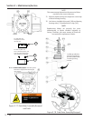
3. Remove four socket head cap screws (457) and
Nord-Lock washers (477) securing mounting plate
(415) to manifold.
4. The command shaft and mounting plate may now
be removed from the compressor.
INSTALLATION
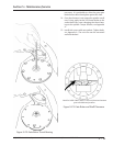
5. Install the command shaft assembly with a new
O-ring (446) on the manifold. Make sure that the
command shaft tongue is engaged in the cross
shaft slot. Rotate the bearing housing so the vent
holes point down, this will prevent water and dust
from entering the vents.
6. Install the actuator mounting plate with the four
socket head cap screws and Nord-Lock washers se-
curing it with proper torque.
7. Perform leak check, see Compressor Unit Leak
Check procedure.
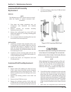
Command Shaft Seal Replacement
REMOVAL
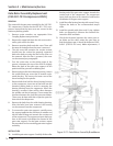
1. Remove bolts (281) holding the shaft seal cover
(218). Insert two of the bolts into the threaded
jacking holes to assist in removing the cover. There
will be a small amount of oil drainage as the cover
is removed.
2. Remove the rotating portion of the shaft seal
(219C).
3. Remove oil seal (230) from cover.
4. Remove the stationary portion of the shaft seal
(219B) from the seal cover using a brass drift and
hammer to tap it out from the back side of the seal
cover.
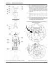
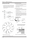
5. Seal with stationary carbon face (219B) and rotat-
ing mirror face (219C).
Figure 5-29. Command Shaft Seal
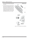
INSTALLATION
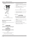
CAUTION
Care must be taken when handling the shaft seal and
mirror face so it is not damaged. Do not touch the
carbon or mirror face as body oil and sweat will cause
the mirror face to corrode.
NOTE
When replacing the stationary members of the seal
on the VSSG 291 thru VSSG 601 the roll pin in the
cover is used only with the seal assembly having a
stationary mirror face. If a seal assembly with a
stationary carbon face is installed, the roll pin must
be removed.
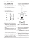
6. To install the carbon cartridge part of the seal in the
seal cover; clean the seal cover, remove protective
plastic from the carbon cartridge, do not wipe or
touch the carbon face. Lubricate the sealing O-ring
with clean compressor lubricating oil. If applicable,
align the hole on the back of the carbon cartridge
with the dowel pin in the seal cover. Install car-
tridge using seal installation tool or similar (see tool
lists).
7. Wipe clean, the compressor input shaft and the
Section 5 • Maintenance/Service