


Return to Section TOC Return to Section TOC Return to Section TOC Return to Section TOC
Return to Master TOC Return to Master TOC Return to Master TOC Return to Master TOC
INSTALLATION
PRO-CUT 60
A-3
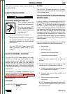
3. Connect the work terminal to a ground within
ten feet of the machine.
a. Use grounding cable that is the same size
as, or larger than, the work cable.
b. Make grounding cable as short as
possible.
c. Connect the ground tightly.
d. Use one of the following ground methods:
(1) Connect to a metal underground water
pipe that is in direct contact with earth for
ten feet or more.
(2) Connect to 3/4" (19mm) galvanized pipe
or a 5/8" (16mm) solid galvanized iron,
steel, or copper rod driven at least eight
feet into the ground.
NOTE: Do Not use the building frame electri-
cal conduit or a long pipe system for ground-
ing the machine. This could result in
increased high frequency interference.
NOTE: When the machine is used in a
metal building, drive several good earth
grounds around the edge of the building. Use
the method in 2 above.
4. Enclose all electrical conductors within 50 feet
(15.2m) of the machine in grounded rigid
metallic conduit or equivalent shielding.
a. Do not use flexible metallic conduit.
5. Make work and torch leads as short and as
close together as possible.
a. Lead length should not exceed 50 feet
(15.2m).
b. Tape leads together when possible.
6. Check torch and work cable rubber insulation
coverings to be sure they do not have any
cracks or cuts that could result in high fre-
quency leakage that could interfere with other
electronic equipment.
a. Use insulated work cables with a high
natural rubber content, such as the Lincoln
Stable-Arc cables. These better resist
high frequency leakage than neoprene or
other synthetic rubber insulated cables.
7. Keep the torch in good repair and all connec-
tions tight to reduce high frequency leakage.
8. Keep all access panels and covers tightly
closed.
Follow these procedures for the best operating
results. Failure to follow these procedures can
cause interference and machine performance
problems.
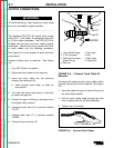
INPUT ELECTRICAL
CONNECTIONS
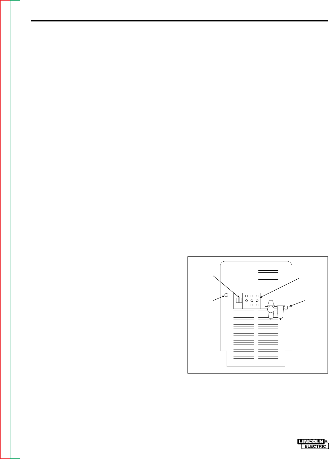
Before installing the machine, check that input
supply voltage, phase, and frequency are the
same as the machine's voltage, phase, and fre-
quency as specified on the machine's rating plate
on the Case Front Assembly. See Figure A.1 for
the location of the machine's input cable entry
opening, terminal block, and reconnect panel
assembly. Input power supply entry is through the
hole in the Case Back Assembly.
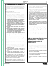
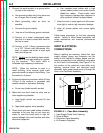
FIGURE A.1 - Case Back Assembly
1. Input Supply Cable Entry Opening
2. Terminal Block
3. Reconnect Panel Assembly
4. Air Pressure Regulator.
➀
➂
➃
➁