


Return to Section TOC Return to Section TOC Return to Section TOC Return to Section TOC
Return to Master TOC Return to Master TOC Return to Master TOC Return to Master TOC
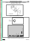
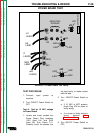
L7941
POWER BOARD
J22
1J22
2J22
1J20
4J22
2J20
3J22
4J20
#40
NEG
C
C
LEADS
NEG
LEAD
H1
LEAD
H1
H2
H2
LEAD
#40
LEADS
J20
G1
G2
B
40
J21
1J21
MOUNTING
SCREWS
TROUBLESHOOTING & REPAIR
PRO-CUT 60
F-23
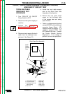
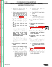
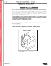
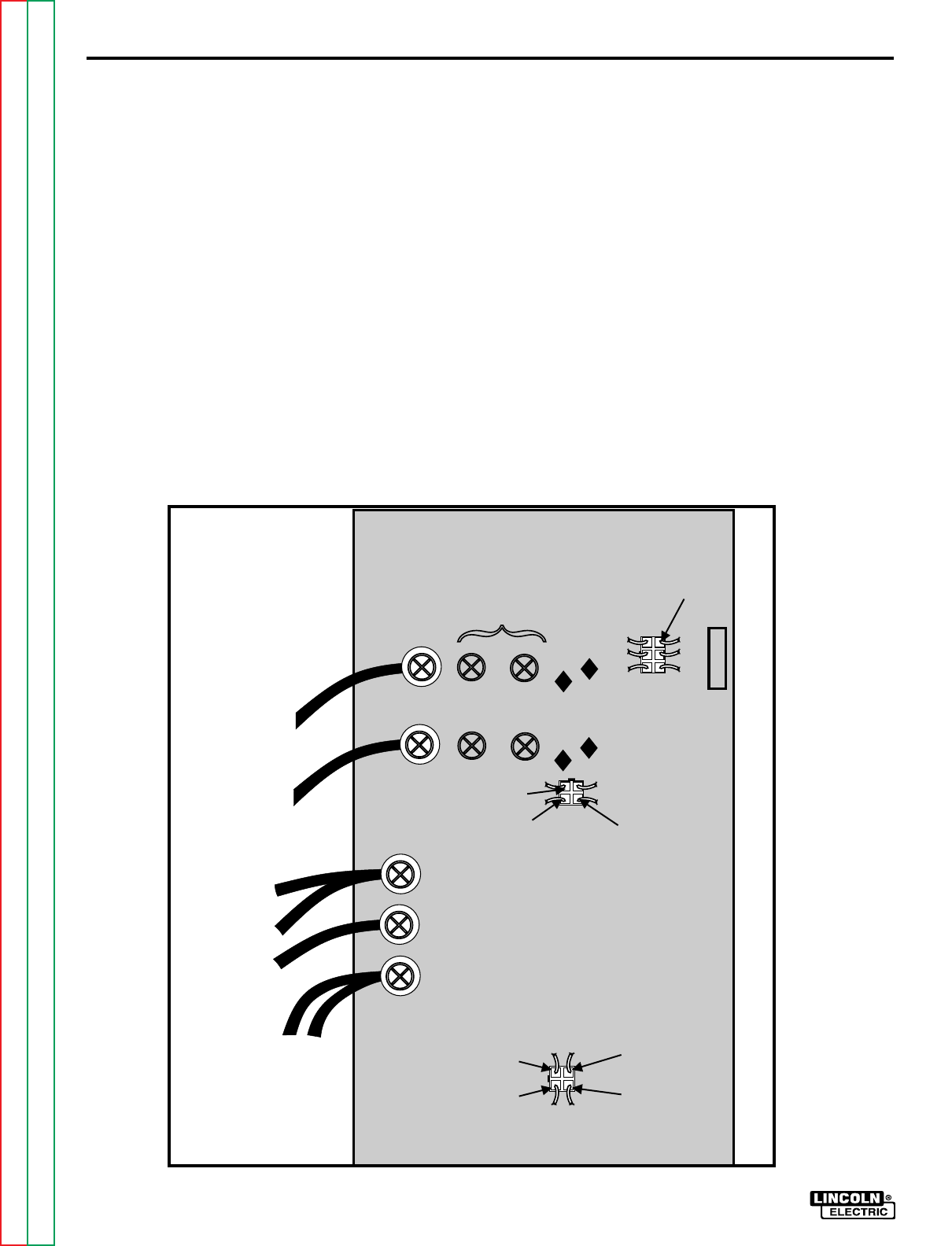
TRANSISTOR MODULE TEST
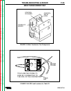
10. Replace the terminal screw
snugly, a little more than finger
tight. The Transistor Module
is mounted behind the Power
Board and the terminal screw
completes the electrical
connection.
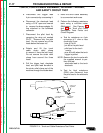
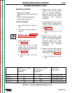
11. Perform the following resi-
tance tests listed in Table F.1:
NOTE: Meter lead polarity must be
observed for these resistance tests.
a. If a low resistance is
measured in both polarities,
the transistor module is
“shorted.” Replace the transis-
tor module, the Power Board,
and the Control Board.
b. If a high resistance is
measured in both polarities,
the transistor module is
“open.” Replace the transistor
module, the Power Board, and
the Control Board.
12. Replace all leads.
a. Torque screws to 17 in./lbs.
( 1.9 N.M.)
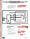
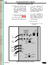
FIGURE F.9-Transistor Module Test Points