


Return to Section TOC Return to Section TOC Return to Section TOC Return to Section TOC
Return to Master TOC Return to Master TOC Return to Master TOC Return to Master TOC
MATERIALS NEEDED
- Analog Volt/Ohmmeter
(Multimeter) with RX10 or RX1000
scale.
- PRO-CUT 60 Wiring Diagrams
- Phillips Head Screwdriver
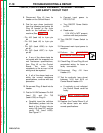
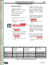
TEST PROCEDURE
1. Turn ON/OFF Power Switch to
OFF.
2. Disconnect main input power to
machine.
3. Perform the CAPACITOR
DISCHARGE PROCEDURE.
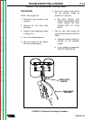
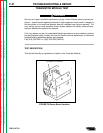
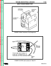
4. Locate Power Board.
See Figure F.8.
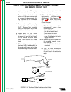
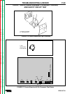
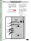
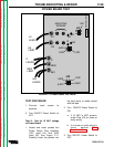
5. Locate and remove the leads
marked #40 by removing the
terminal screw connecting them
to the Power Board.
See Figure F.9.
a. Move the leads out of the
way.
6. Replace the terminal screw
snugly, a little more than finger
tight. The Transistor Module is
mounted behind the Power
Board and the terminal screw
completes the electrical
connection.
7. Locate and remove the one lead
marked NEG by removing the
terminal screw connecting it to
the Power Board.
See Figure F.9.
a. Move the lead out of the
way.
8. Replace the terminal screw
snugly, a little more than finger
tight. The Transistor Module is
mounted behind the Power
Board and the terminal screw
completes the electrical
connection.
9. Remove the two leads marked
C by removing the terminal
screw connecting them to the
Power Board. See Figure F.9.
a. Move the lead out of the
way.
TROUBLESHOOTING & REPAIR
PRO-CUT 60
F-22
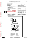
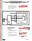
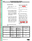
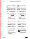
TRANSISTOR MODULE TEST
TEST
TEST B
TEST C
TEST D
C
#40
#40
Neg
#40
C
Neg
#40
1,000 ohms or less
4,500 ohms or higher
4,500 ohms or higher
1,000 ohms or less
NEGATIVE (-) PROBE
TO TERMINAL
MARKED:
POSITIVE (+) PROBE
TO TERMINAL
MARKED:
EXPECTED
RESISTANCE
TABLE F.1 - Transistor Module Resistance Tests