


Return to Section TOC Return to Section TOC Return to Section TOC Return to Section TOC
Return to Master TOC Return to Master TOC Return to Master TOC Return to Master TOC
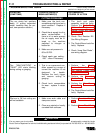
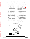
8. Disconnect Plug J5 from its
header on the Control Board.
9. Test for zero ohms (continuity)
from the following test points on
Plug J5 header to the 4-pin
leads on the bulkhead of the
machine (See Figure F.7):
- Pin 4J5 (lead #4) to 4-pin pin
#4
- Pin 3J5 (lead #2) to 4-pin pin
#2
- Pin 6J5 (lead #336) to 4-pin
pin #1
- Pin 8J5 (lead #337) to 4-pin
pin #3
a. If any of the above tests do
not agree with the expected nor
mal resistance specifications,
then Plug J5 on the Control
Board, the torch 4-pin
receptacle, or the associated
wiring must be repaired.
b. If all of the above tests are
within the normal resistance
specifications, continue with test
procedure.
10. Re-connect Plug J5 back into its
header.
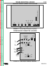
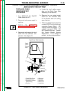
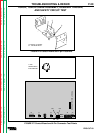
11. Test for 24 VAC between Pin 5J5
(lead C1) and Pin 7J5
(lead # 335) on Plug J5.
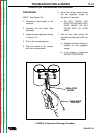
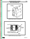
a. Carefully insert the volt/ohm
(Multimeter) probes into the
back of the J5 plug into pin
cavity 5J5 (lead C1) and pin
cavity 7J5 (lead #335).
See Figure F.1.
b. Connect input power to
PRO-CUT 60.
c. Turn ON/OFF Power Switch
to ON.
d. Read meter.
- If 24 VAC is NOT present,
continue with test procedure.
12. Turn ON/OFF Power Switch to
OFF.
13. Disconnect main input power to
machine.
14. Perform the CAPACITOR
DISCHARGE PROCEDURE.
15. Check Plug J10 and Plug J5 and
associated wiring for loose or
faulty connections.
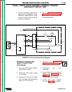
16. Disconnect Plug J10 from
Header J10.
17. Test for continuity (zero ohms)
between 3J10 and 6J10 on
Control Board Header J10.
a. If continuity is not indicated,
the Control Board could be
faulty.
18. Perform MAIN TRANSFORMER
TEST.
19. Replace the Control Board if all
of the above tests are within
normal specifications.
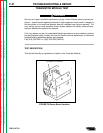
TROUBLESHOOTING & REPAIR
PRO-CUT 60
F-19
TORCH, TORCH CABLE ASSEMBLY, INTERNAL TRIGGER,
AND SAFETY CIRCUIT TEST