


Return to Section TOC Return to Section TOC Return to Section TOC Return to Section TOC
Return to Master TOC Return to Master TOC Return to Master TOC Return to Master TOC
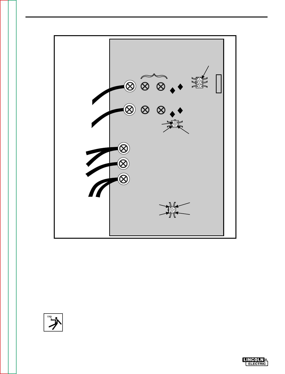
L7941
POWER BOARD
J22
1J22
2J22
1J20
4J22
2J20
3J22
4J20
#40
NEG
C
C
LEADS
NEG
LEAD
H1
LEAD
H1
H2
H2
LEAD
#40
LEADS
J20
G1
G2
B
40
J21
1J21
MOUNTING
SCREWS
TROUBLESHOOTING & REPAIR
PRO-CUT 60
F-39
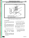
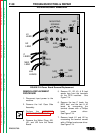
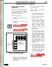
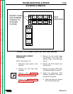
POWER BOARD REMOVAL
REMOVAL/REPLACEMENT
PROCEDURE
1. Disconnect input power to the
machine.
2. Remove the Left Case Side
Assembly.
3. Perform the CAPACITOR
DISCHARGE PROCEDURE.
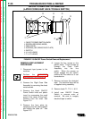
4. Remove the Molex Plugs J20,
J21, and J22 from the Power
Board.
5. Remove G1, G2, 40, & B lead
spade lugs from the terminals
on the SCR modules. See
Figure F.14.
6. Remove the two C leads, the
NEG lead, and the two # 40
leads by unscrewing the
terminal screws with a Phillips
head screw driver.
See Figure F.14.
7. Remove leads H1 and H2 by
unscrewing the terminal screws
with a Phillips head screw driver.
See Figure F.14.
FIGURE F.14-Power Board Removal/Replacement