


Return to Section TOC Return to Section TOC Return to Section TOC Return to Section TOC
Return to Master TOC Return to Master TOC Return to Master TOC Return to Master TOC
THEORY OF OPERATION
PRO-CUT 60
E-2
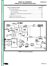
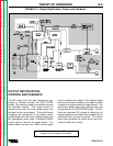
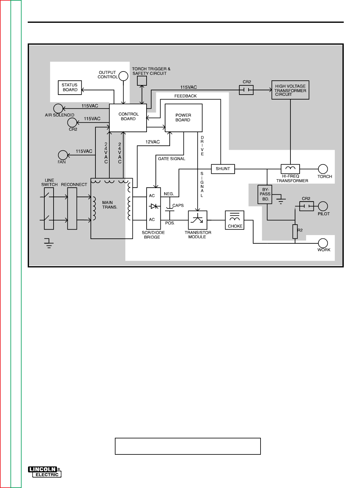
FIGURE E.3 - Output Rectification, Control and Feedback
OUTPUT RECTIFICATION,
CONTROL AND FEEDBACK
The AC output from the main transformer sec-
ondary is rectified through the SCR/ DIODE
bridge. The machine output is controlled through
the transistor module. The output current is
sensed at the shunt, as a low voltage signal, and
fed back to the control board. The control board
compares the commands of the output control
potentiometer with the shunt feedback signal and
the appropriate pulse width modulated (PWM)
control signal is sent to the power board. The
power board converts the PWM control signal
into an isolated drive signal. This isolated signal
drives the transistor module to the optimum level
to obtain the desired machine output current. The
control and power board also generate the gate
firing pulses for the SCR/DIODE bridge. The rec-
tified and controlled DC voltage is filtered by the
output capacitors and choke and is applied to the
machine's torch and work terminals. The control
board also operates the status board and com-
mands the pilot arc circuitry.
NOTE: Unshaded areas of Block Logic
Diagram are the subject of discussion