


Return to Section TOC Return to Section TOC Return to Section TOC Return to Section TOC
Return to Master TOC Return to Master TOC Return to Master TOC Return to Master TOC
INSTALLATION
PRO-CUT 60
A-5
AIR INPUT CONNECTIONS
Supply the PRO-CUT 60 with clean compressed
air or nitrogen.
• Supply pressure must be between 70 psi
and 120 psi (482 kPa and 827 kPa).
• Flow rate should be approximately 4.7
cfm (133 I/min.).
NOTE: Oil in the air supply to the PRO-CUT 60
can cause severe problems. Use only a clean air
supply.
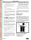
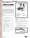
1. Connect the air supply to the PRO-CUT 60
regulator.
a. Remove the plastic thread protector from
the machine's regulator input port located
on the back of the machine. Refer to figure
A.1.
-The input port is a 1/4" (6.3mm) NPT
thread.
b. Connect the air supply to the machine reg-
ulator with an appropriate gas connection
fitting. Sealing the connection with Teflon
tape is recommended.
2. Tighten the air fitting connection to prevent
leakage.
-Do not overtighten.
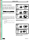
NOTE: When using nitrogen gas from a cylinder,
the cylinder must have a pressure regulator.
• Maximum psi from nitrogen gas cylinder to
PRO-CUT 60 regulator should never
exceed 120 psi (827 kPa).
• Install a hose between the nitrogen gas
cylinder regulator and the PRO-CUT 60
regulator's gas inlet.
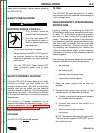
CYLINDER could explode if damaged.
• Keep cylinder upright and chained to a
fixed support.
• Keep cylinder away from areas where it
could be damaged.
• Never lift machine with cylinder attached.
• Never allow the cutting torch to touch the
cylinder.
• Keep cylinder away from live electrical
parts.
• Maximum inlet pressure 120 psi
(827kPa).
__________________
WARNING