


Return to Section TOC Return to Section TOC Return to Section TOC Return to Section TOC
Return to Master TOC Return to Master TOC Return to Master TOC Return to Master TOC
TROUBLESHOOTING & REPAIR
PRO-CUT 60
F-16
TORCH, TORCH CABLE ASSEMBLY, INTERNAL TRIGGER,
AND SAFETY CIRCUIT TEST
TORCH AND CABLE
RESISTANCE TEST
PROCEDURE
1. Turn PRO-CUT 60 ON/OFF
Power Switch to OFF.
2. Disconnect main power supply to
machine.
3. Perform the CAPACITOR
DISCHARGE PROCEDURE.
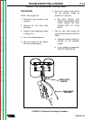
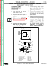
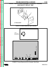
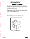
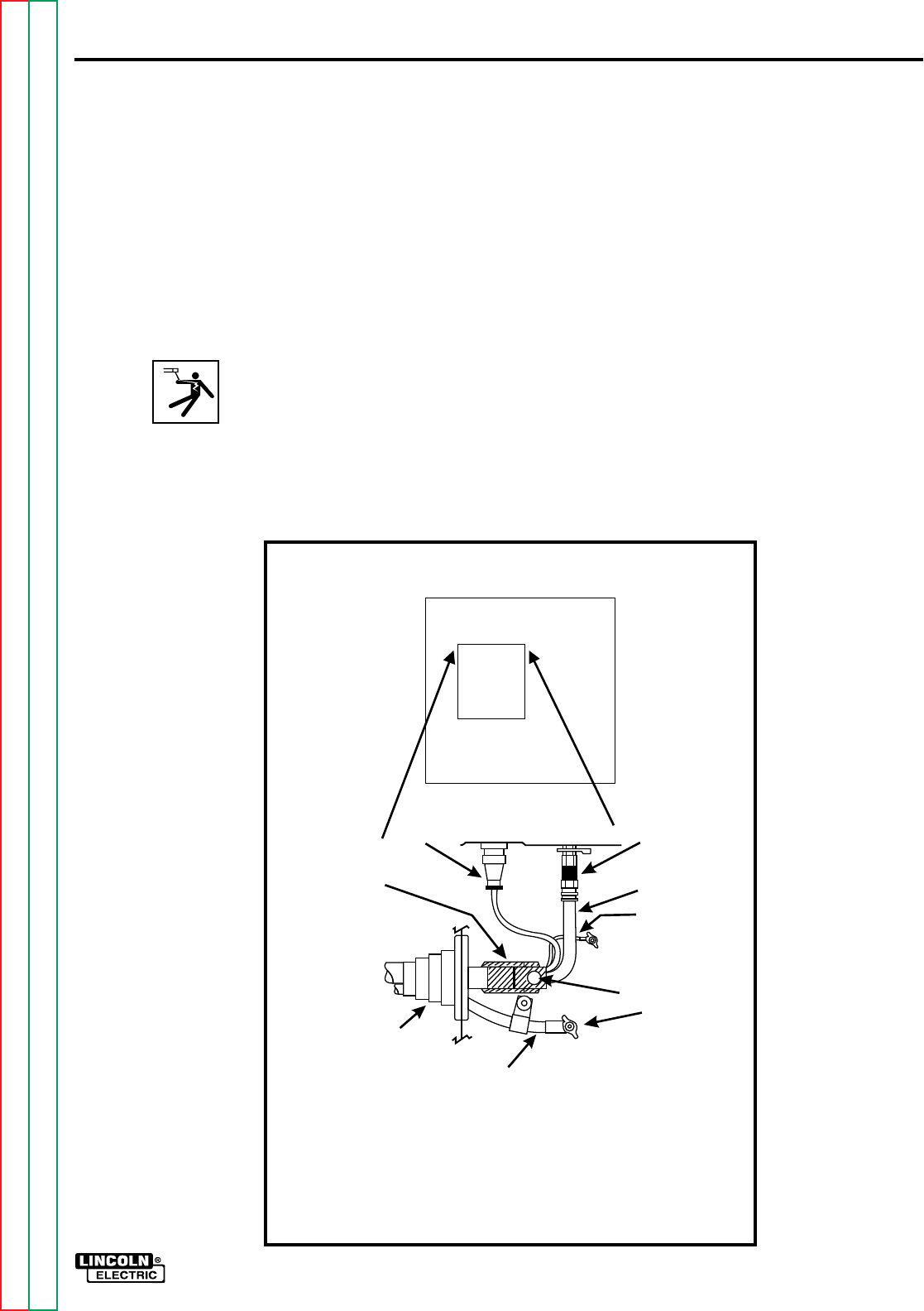
4. Disconnect and remove the torch
cable from the bulkhead com-
partment. See Figure F.3.
a. Locate the torch cable access
door on the Right Case Side
Assembly of the machine.
b. Remove the one sheet metal
screw on the left-hand side
of the access door and swing
open the door.
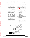
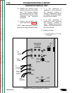
c. Test for a voltage across the stud
marked WORK and the bulkhead
connector (brass fitting). NO
voltage should be present. If a
voltage is present, STOP. DO
NOT perform this test. Contact
the Lincoln Electric Service
Department. If no voltage is
present, continue test procedure.
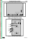
➀
➁
➂
➃
➄
➅
➆
➇
➈
PILOT
WORK
➀ Strain Relief Clamp
➁ 4-Pin Connector
➂ Bulkhead Connector
(Brass Fitting)
➃ Gas Line
Torch
Cable
Access
Door
Right Case Side Assembly
➄ Pilot Lead
➅ Bolt Hole
➆ Work Stud
➇ Work Lead
➈ Cable Boot
FIGURE F.3 - Torch Cable Connections