


Return to Section TOC Return to Section TOC Return to Section TOC Return to Section TOC
Return to Master TOC Return to Master TOC Return to Master TOC Return to Master TOC
TROUBLESHOOTING & REPAIR
PRO-CUT 60
F-6
Observe Safety Guidelines
detailed in the beginning of this manual.
TROUBLESHOOTING GUIDE
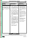
PROBLEMS
(SYMPTOMS)
The air begins to flow, the
"OUTPUT ON" LED lights for a
short time, but no pilot arc is
established.
POSSIBLE AREAS OF
MISADJUSTMENT(S)
1. The pilot arc will shut off
after 2.5 seconds unless it is
brought in contact with the
work and the cutting arc is
established. This is a
normal condition.
2. Check the torch consum-
ables to be sure they are
installed properly. Make
sure they are not dirty or
greasy and are in good con
dition. Replace the consum-
ables if necessary.
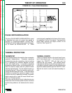
3. Check for the presence of
high frequency "spark" at the
spark gap, located inside
the right panel of the
machine. The "spark" will
normally be present for a
second or two when the
torch trigger is pulled.
4. Check the high frequency
spark gap setting. It should
be set at .060"(1.5mm).
DISCONNECT ALL INPUT
POWER BEFORE ADJUST-
ING THE HIGH FREQUEN-
CY CIRCUIT.
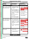
5. The machine's upper com-
partment could be dirty, blow
out the upper compartment
with compressed air.
RECOMMENDED
COURSE OF ACTION
1. The torch and cable assembly
may be faulty. Perform Torch,
Torch Cable Assembly, and
Internal Trigger and Safety
Circuit Tests.
If the high frequency "spark"
is present at the spark gap (for
1 second) go to step #3.
2. If the high frequency "spark" is
not present at the spark gap,
check that the pilot control
relay (CR2) contacts close
when the torch trigger is
pulled.
a. If pilot control relay (CR2)
contacts close when torch trig-
ger is pulled, perform High
Voltage Transformer Test.
b. If pilot control relay (CR2)
contacts DO NOT close, test
for 115 VAC between leads
#36 and #31 on pilot control
relay (CR2) when the torch trig-
ger is pulled. Refer to wiring
diagram. If 115 VAC is present,
pilot control relay (CR2)
could be faulty.Replace.
c. If 115 VAC IS NOT present,
check plug J10 on Control
Board and associated wires
for loose or faulty connections.
Refer to wiring diagram. If
none are found, Control Board
could be faulty. Replace.
3. Check resistor R2. Normal
resistance is 2 ohms. Refer to
wiring diagram.
4. Check resistor R7. Normal
resistance is 5 ohms. Refer to
wiring diagram.
5. Check the two "jump-start"
diodes mounted on a plastic
board just in front of the shunt.
Refer to wiring diagram.
6. If check 3, 4, and 5 are OK,
the Control Board could be
faulty. Replace.
If for any reason you do not understand the test procedures or are unable to perform the tests/repairs safely, contact the Lincoln
Electric Service Department for technical troubleshooting assistance before you proceed call 216-383-2531 or 1-800-833-9353.
OUTPUT PROBLEMS
CAUTION