


Return to Section TOC Return to Section TOC Return to Section TOC Return to Section TOC
Return to Master TOC Return to Master TOC Return to Master TOC Return to Master TOC
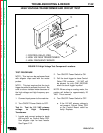
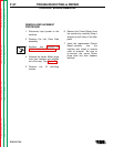
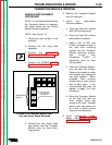
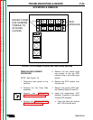
8. Remove the four mounting
Phillips head screws holding the
Power Board to the SCR
module.
9. Remove the two nylon nuts from
the studs on which the Power
Board is mounted with a 7/16”
nut driver.
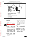
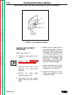
10. Remove the Power Board by
pulling it out clear of the studs
and lifting it straight up out of
the machine.
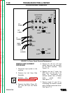
11. Install replacement Power Board
by sliding it over the mounting
studs.
12. Replace the nylon nuts loosely
on the mounting studs so the
Power Board position can be
adjusted when installing the
mounting and terminal screws.
13. Install the four mounting screws
finger tight.
14. Connect leads H1 and H2 to the
SCR modules with the terminal
screws finger tight.
15. Connect leads C (two wires),
NEG, and #40 (two wires) with
the terminal screws finger tight.
16. Tighten the six screws connect-
ing the Power Board to the SCR
modules to 35 in/lbs (3.9 N.M.).
17. Tighten the three screws
connecting the C, NEG, and #40
leads to the Power Board and
the Transistor Module to
17 in/lbs (1.9 N.M.).
18. Tighten the nylon nuts on the
mounting studs.
19. Reconnect tightly all Molex
Plugs (J20, J21, and J22) and
plug in spade lug leads marked
G1, G2, #40, and B through the
Power Board to terminals on the
SCR modules.
TROUBLESHOOTING & REPAIR
PRO-CUT 60
F-40
POWER BOARD REMOVAL