


Return to Section TOC Return to Section TOC Return to Section TOC Return to Section TOC
Return to Master TOC Return to Master TOC Return to Master TOC Return to Master TOC
TROUBLESHOOTING & REPAIR
PRO-CUT 60
F-18
INTERNAL TRIGGER AND
SAFETY CIRCUIT TEST
PROCEDURE
1. Turn the PRO-CUT 60 ON/OFF
Power Switch to OFF.
2. Disconnect input power supply
to machine.
3. Remove the roof and the Right
and Left Case Side Assemblies
using a 5/16” nut driver.
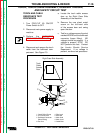
4. Perform the CAPACITOR
DISCHARGE PROCEDURE.
5. Disconnect the 4-pin
connector.
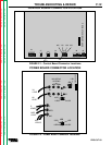
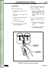
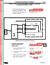
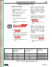
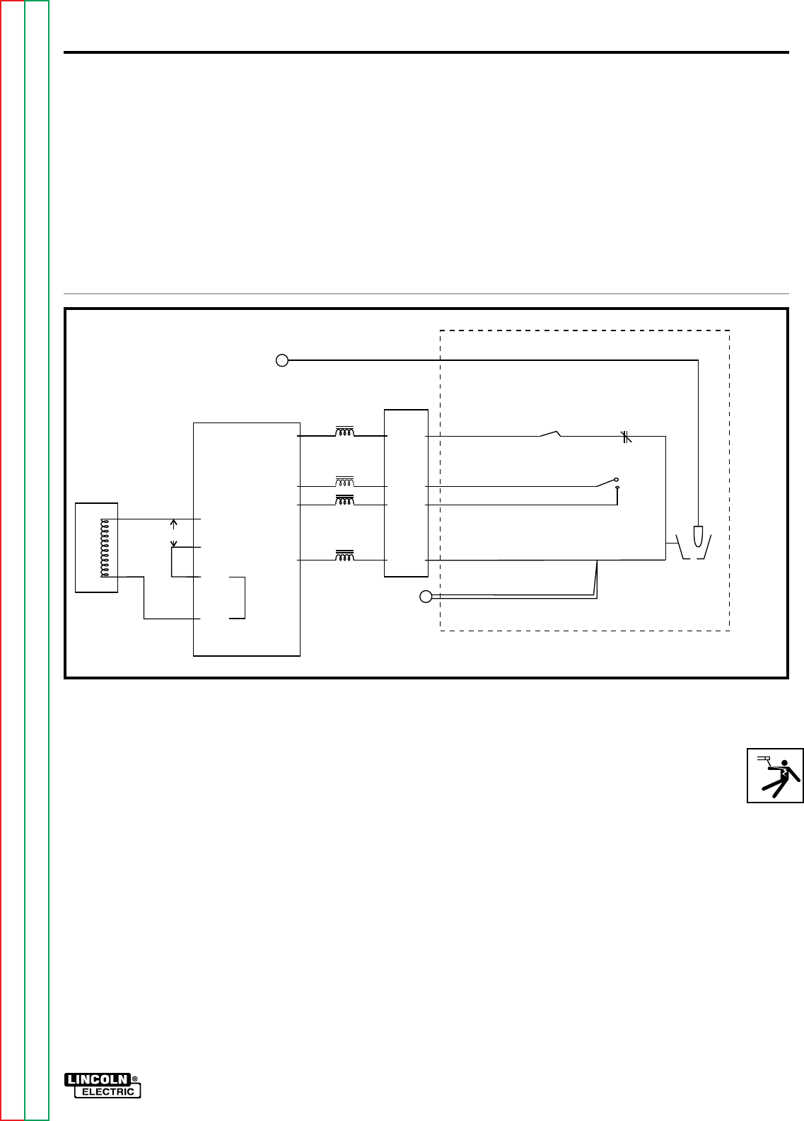
6. Locate Plug J5 on the Control
Board. See Figure F.6 and
Figure F.1 for the location of the
Control Board and Plug J5.
7. Locate the 4-pin recepta-
cle. See Figure F.6 for location.
3J10
6J5
5J5
24 VAC
24 VAC
3J5
#2
BLUE
NOZZLE
ELECTRODE
ELECTRODE
PILOT
CONE
SWITCH
SAFETY WIRE
N.C.
THERMOSTAT
GUN TRIGGER
TORCH HEAD
CONDUCTOR IN GAS TUBE
#4 PURPLE
#336 RED
#337 WHITE
Pin #2
Pin #4
Pin #1
Pin #3
7J5
C1
#3L
#335
4J5
6J10
8J5
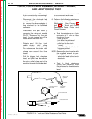
TORCH, TORCH CABLE ASSEMBLY, INTERNAL TRIGGER,
AND SAFETY CIRCUIT TEST
c. If any of the above tests do not
agree with the expected normal
resistance specifications, then
the torch and/or cable must be
repaired or replaced.
d. Go to INTERNAL TRIGGER
AND SAFETY CIRCUIT TEST if
all resistance values are within
the specified range.
FIGURE F.5-Torch and Cable Wiring Diagram