


Return to Section TOC Return to Section TOC Return to Section TOC Return to Section TOC
Return to Master TOC Return to Master TOC Return to Master TOC Return to Master TOC
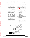
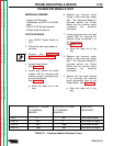
d. Disconnect the trigger lead
4-pin connector by unscrewing it.
e. Disconnect the electrode lead
using a 9/16” open-end wrench
to remove the brass adaptor fit-
ting attached to the bulkhead
connector.
f. Disconnect the pilot lead by
removing the wing nut marked
PILOT. Remove only the pilot
lead. Do not remove any of the
leads below the brass nut.
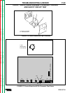
g. Rotate and lift the torch
cable strain relief clamp
to remove it from the bolt head.
Do not remove the strain relief
clamp from around the three
leads.
h. Pull the trigger lead, electrode
lead, and pilot lead bundled in
the strain relief clamp out of the
machine through the rubber boot.
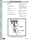
5. Move the torch cable assembly
to a convenient work area.
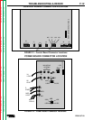
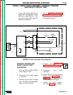
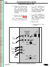
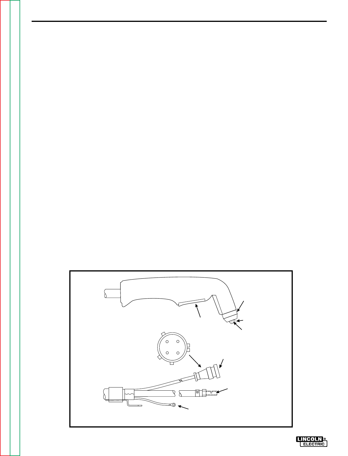
6. Perform the following resistance
tests using a volt/ohm meter
(Multimeter). See Figures F.4.
and F.5 for Torch and Cable
Resistance Tests Points and
Circuit Diagram.
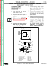
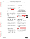
a. Test for resistance on 4-pin
connector of 1 ohm or less
(continuity) from:
- pins #1 to #3.
- pin #3 to the pilot lead.
- pilot lead to the torch
nozzle.
- pins #2 to #4 when the torch
trigger is pulled.
NOTE: Remove the torch nozzle with
the supplied wrench to per-
form this test.
- electrode lead to the torch
electrode.
b. Test for high resistance
(500K ohm minimum) from
the pilot lead to the electrode
lead.
PILOT LEAD
TRIGGER
SHIELD CUP
ASSEMBLY
ELECTRODE
ASSEMBLY
4 - PIN CONNECTOR
ELECTRODE LEAD
4- PIN CONNECTOR
(END VIEW)
NOZZLE
2
4
1
3
TROUBLESHOOTING & REPAIR
PRO-CUT 60
F-17
TORCH, TORCH CABLE ASSEMBLY, INTERNAL TRIGGER,
AND SAFETY CIRCUIT TEST
FIGURE F.4 - Torch and Cable Resistance Test Points