


Return to Section TOC Return to Section TOC Return to Section TOC Return to Section TOC
Return to Master TOC Return to Master TOC Return to Master TOC Return to Master TOC
Test D: Test for 0.2 VDC to 0.3
VDC Gate Drive Voltages to the
SCR Module.
NOTE: This test requires that the
torch trigger be pulled to activate the
circuit. Be sure to use an isolated
meter because of the high voltage
and high frequency produced.
NOTE: This test requires testing DC
voltages. Polarity must be observed.
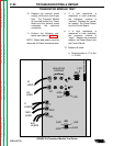
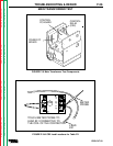
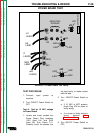
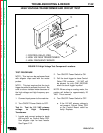
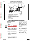
1. Locate and insert probes into
the following Power Board plug
locations (See Figure F.11):
a. Insert the NEGATIVE probe
into Plug 1J21 (lead #383 -)
lead cavity.
b. Insert the POSITIVE probe
into Plug 3J20 (lead G2 +)
lead cavity.
2. Turn the ON/OFF Power Switch
to ON.
3. Pull torch trigger. When air pre-
flow times out and the pilot arc
is established, 0.2 VDC to 0.3
VDC should be present.
4. Release torch trigger.
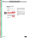
5. Locate and insert probes into
the following Power Board plug
locations (See Figure F.11):
a. Insert the NEGATIVE probe
into Plug 1J21 (lead #383 -)
lead cavity.
b. Insert the POSITIVE probe
into Plug 4J20 (lead G1 +)
lead cavity.
2. Turn the ON/OFF Power Switch
to ON.
3. Pull torch trigger. When air pre-
flow times out and the pilot arc
is established, 0.2 VDC to 0.3
VDC should be present.
4. Release torch trigger. Turn
ON/OFF Power Switch to OFF.
a. If specific voltages ARE
NOT present, check Power
Board Plugs J20 and J21
and Control Board Plug J6
for loose or faulty wiring.
b. If no loose or faulty wiring is
found, the Power Board,
Control Board, or SCR
module could be faulty.
Replace.
TROUBLESHOOTING & REPAIR
PRO-CUT 60
F-30
POWER BOARD TEST