


Return to Section TOC Return to Section TOC Return to Section TOC Return to Section TOC
Return to Master TOC Return to Master TOC Return to Master TOC Return to Master TOC
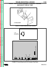
L7941
POWER BOARD
J22
1J22
2J22
1J20
4J22
2J20
3J22
4J20
#40
NEG
C
C
LEADS
NEG
LEAD
H1
LEAD
H1
H2
H2
LEAD
#40
LEADS
J20
G1
G2
B
40
J21
1J21
MOUNTING
SCREWS
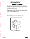
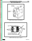
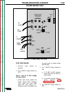
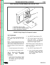
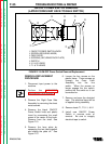
TEST PROCEDURE
1.Connect input power to
machine.
2.Turn ON/OFF Power Switch to
OFF.
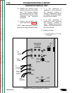
Test A: Test for 12 VAC voltage
to Power Board
1.Locate and insert probes into
Power Board Plug locations
1J22 (lead H4) and 3J22
(lead H3). See Figure F.11.
Carefully insert the probes into
the lead cavity to make contact
with the lead.
2.Turn ON/OFF Power Switch to
ON.
a.If 12 VAC is NOTpresent,
check Plug J22 for loose or
faulty wiring.
b If no loose or faulty wiring is
found, perform Main
Transformer Test.
3.Turn ON/OFF Power Switch to
OFF.
FIGURE F.11-Power Board Test Points
TROUBLESHOOTING &REPAIR
PRO-CUT 60
F-28
POWER BOARD TEST