


Return to Section TOC Return to Section TOC Return to Section TOC Return to Section TOC
Return to Master TOC Return to Master TOC Return to Master TOC Return to Master TOC
TROUBLESHOOTING & REPAIR
F-54 F-54
RANGER 300 D AND 300 DLX
FIELD CAPACITOR AND/OR RECTIFIER BRIDGE REMOVAL
AND REPLACEMENT (continued)
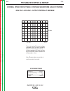
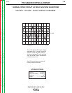
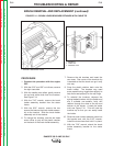
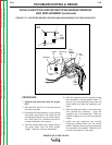
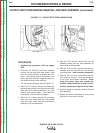
FIGURE F.15 – RECTIFIER BRIDGE LOCATION AND DISCHARGING THE FIELD CAPACITOR
PROCEDURE
1. Conduct this procedure with the engine
OFF.
2. With the 5/16” and 3/8” nut drivers, remove
the right case side.
3. Discharge the field capacitor by connecting
the jumper wire clips on the white and the
red wire terminals on the top of the capac-
itor. See Figure F.15. Leave the clips on for
at least 5 seconds, then remove.
4. With the needle nose pliers, gently remove
the seven wires from the field rectifier
bridge. Label the wires for reassembly.
5. Both the capacitor and the rectifier bridge
are mounted in a molded plastic holder. To
remove it, pull the assembly away from the
metal baffle and slide the assembly out-
ward.
6. With the diagonal cutters, cut the wire wrap
from around the capacitor. Snap the
capacitor out of the assembly. Slide the
rectifier bridge out of its part of the plastic
holder.
7. Install the new capacitor and rectifier
bridge by inserting them into the plastic
holder. Replace the wire wrap that secures
the capacitor to the holder. Slide the hold-
er back into position in the panel.
200
200A
200B
201
201A
200
200A
200B
7
9
+
_
AC
AC
7
201
201A
9
Field
Bridge
Rectifier
Retaining
Tab
Cable
Tie
Capacitor