


Return to Section TOC Return to Section TOC Return to Section TOC Return to Section TOC
Return to Master TOC Return to Master TOC Return to Master TOC Return to Master TOC
TROUBLESHOOTING & REPAIR
F-55 F-55
RANGER 300 D AND 300 DLX
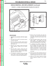
FIELD CAPACITOR AND/OR RECTIFIER BRIDGE REMOVAL
AND REPLACEMENT (continued)
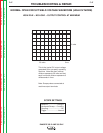
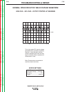
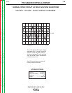
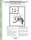
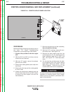
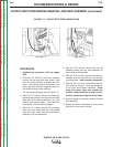
8. Connect the wires to the proper terminals
on the rectifier bridge. See Figure F.15
and the Wiring Diagram.
Leads #200, #200A and #200B are piggy-
backed on the positive (+) terminal.
Depending on the bridge used, this corner
may be beveled and/or marked with a +
sign.
Leads #201 and #201A are located on the
negative (-) terminal, which will always be
located diagonally across from the posi-
tive (+) terminal.
The two leads #7 and #9 are the AC side
of the bridge and attach to the other two
corners of the rectifier. Either lead can go
on either terminal.
9. Check that the leads are not grounded and
also check for clearance and tightness.
10. Install the right case side.