


Return to Section TOC Return to Section TOC Return to Section TOC Return to Section TOC
Return to Master TOC Return to Master TOC Return to Master TOC Return to Master TOC
TROUBLESHOOTING & REPAIR
F-63 F-63
RANGER 300 D AND 300 DLX
OUTPUT CAPACITOR BANK REMOVAL AND REPLACEMENT
(RANGER 300 DLX ONLY) (continued)
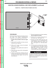
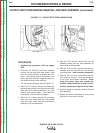
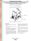
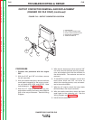
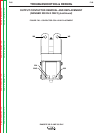
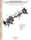
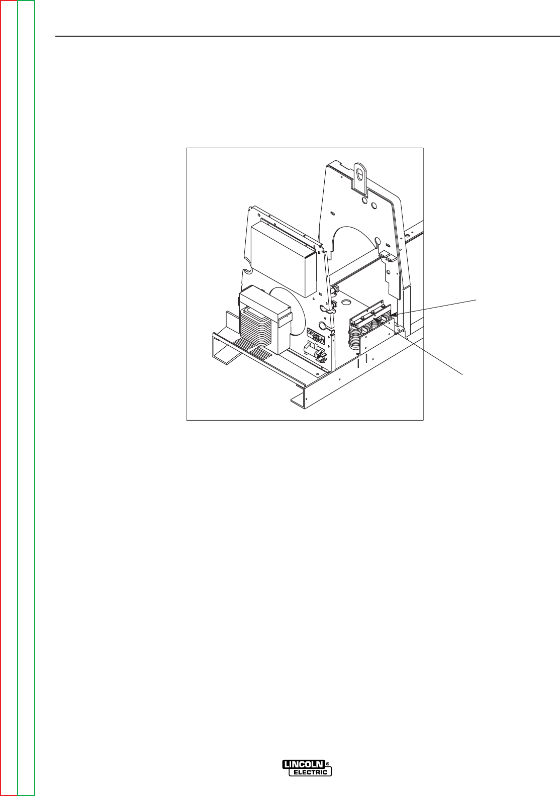
FIGURE F.18 - OUTPUT CAPACITOR BANK
PROCEDURE
1. Conduct this procedure with the engine
OFF.
2. With the 5/16” and 3/8” nut drivers, remove
the right case side.
3. With the voltmeter, check the voltage across
each of the four output capacitors. If a volt-
age is present, use a 25-watt resistor to dis-
charge each capacitor. See Figure F.18.
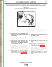
4. With the 1/2” wrench, remove the two nuts,
bolts, and washers holding the two heavy
leads (W14 and W3) and the two small leads
(#236A negative and #245 red, positive) to
the capacitor bank buss bars. Note lead
placement.
5. With the 5/16” nut driver, remove the four
mounting screws holding the capacitor bank
assembly to the base of the machine.
6. Carefully remove the capacitor bank assem-
bly.
7. To replace the capacitor bank assembly,
mount the assembly to the base of the
machine with the four screws previously
removed.
8. With the 1/2” wrench, attach the two heavy
leads and small lead previously removed to
the positive and negative capacitor buss
bars. Observe capacitor polarity.
9. Install the right case side.
CAPACITOR (4)
BUSS BAR (2)