


WELDING OPERATION
Do not attempt to use this equipment until you have
thoroughly read the engine manufacturer’s manual
supplied with your welder. It includes important safe-
ty precautions, detailed engine starting, operating and
maintenance instructions, and parts lists.
ELECTRIC SHOCK can kill.
• Do not touch electrically live parts or
electrode with skin or wet clothing.
• Insulate yourself from work and ground
• Always wear dry insulating gloves.
FUMES AND GASES can be danger-
ous.
• Keep your head out of fumes.
• Use ventilation or exhaust to remove
fumes from breathing zone.
MOVING PARTS can injure.
• Do not operate with doors open or
guards off.
• Stop engine before servicing.
• Keep away from moving parts.
WELDING SPARKS can cause fire or
explosion.
• Keep flammable material away.
ARC RAYS can burn.
• Wear eye, ear and body protection.
See additional warning information throughout this
operator’s manual.
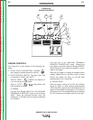
GENERAL INFORMATION
The RANGER 300 machines can deliver from 45 to 300
amps of constant current for AC/DC stick welding.
The Ranger 300 DLX can deliver 45 to 300 amps of
constant voltage current for DC semiautomatic wire
feed welding. The Ranger 300 D can deliver 45 to 200
amps of constant voltage current for DC semiauto-
matic wire feed welding. AC/DC constant current TIG
welding is possible across the entire range from 45 to
300 amps, although 250 amps is the maximum rec-
ommended for AC TIG welding of aluminum.
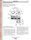
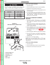
Output can be adjusted by setting the POLARITY
SWITCH, the OUTPUT RANGE dial, and the FINE
CONTROL dial on the output control panel to the set-
tings that are best for your selected welding process.
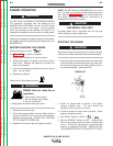
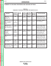
AC/DC STICK (CONSTANT CURRENT)
WELDING
1. Remove the flange nuts from output terminals and
place the work and electrode welding cables over
the terminals. See Figure B.4. Replace and tight-
en the flange nuts securely. Be sure the connec-
tions are tight.
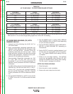
2. Select the appropriate electrode. See “Welding
Tips 1” included with your RANGER 300.
3. Attach the work clamp securely to the work you are
welding.
4. Insert the electrode into the electrode holder.
5. Set the IDLER CONTROL to AUTO and start the
diesel engine.
6. Set the RANGE switch to a setting equal to or
slightly lower than the welding current recom-
mended for the electrode being used. For the best
welding performance, always set the RANGE
switch to the lowest CC-blue setting that will give
the desired weld current. This will assure that the
OUTPUT dial is set towards the high end of the
dial. If the OUTPUT dial is set at 10 and the weld-
ing current is set to low, move the RANGE switch
to the next highest setting.
7. Set the POLARITY switch to the desired polarity
(CC-blue setting).
8. Set the OUTPUT control. For stick welding, always
use a setting between 5 and 10 on the dial (blue
range).
9. Strike an arc and begin welding. The OUTPUT
control can be adjusted while welding.
OPERATION
B-11 B-11
RANGER 300 D AND 300 DLX
Return to Section TOC Return to Section TOC Return to Section TOC Return to Section TOC
Return to Master TOC Return to Master TOC Return to Master TOC Return to Master TOC
CAUTION