


Return to Section TOC Return to Section TOC Return to Section TOC Return to Section TOC
Return to Master TOC Return to Master TOC Return to Master TOC Return to Master TOC
TROUBLESHOOTING & REPAIR
F-34 F-34
RANGER 300 D AND 300 DLX
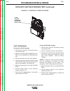
AUXILIARY AND FIELD WINDING TEST (continued)
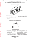
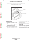
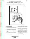
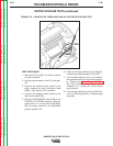
FIGURE F.9 – LOCATION OF LEADS #3A AND #3B
TEST PROCEDURE
To test the 115 VAC winding:
1. With the 5/16” and 3/8” nut drivers, remove
the case left side.
2. Make sure that the LOCAL/REMOTE switch
(S8) is in the CONTROL AT WELDER posi-
tion.
3. Set the voltmeter to the AC volts position.
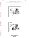
4. Connect the volt/ohmmeter probes to leads
#3A and #3B where they connect to the 15
amp circuit breakers. See Figure F.9.
5. Start the engine and run it at high idle (3700
RPM).
6. Set the output control to the maximum
position (position 10).
7. Check the AC voltage reading. It should be
approximately 125 VAC.
To test the 230 VAC winding:
1. With the 5/16” and 3/8” nut drivers, remove
the case left side.
2. Set the voltmeter to the AC volts position.
3. Connect the volt/ohmmeter probes to leads
#6 and #3 where they connect to the 50
amp circuit breakers. See the Wiring
Diagram.
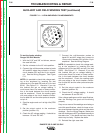
NOTE: It is easier to insert the probes directly
into the receptacle to perform this test.
However, the probes may not reach in far
enough to make or keep a good connection.
4. Start the engine and run it at high idle (3700
RPM).
5. Set the output control to the maximum
position (position 10).
6. Check the AC voltage reading. It should be
approximately 240 VAC.
15 AMP
CB LEADS
#3A AND #3B
LOCATED ON
REAR OF PANEL