


Return to Section TOC Return to Section TOC Return to Section TOC Return to Section TOC
Return to Master TOC Return to Master TOC Return to Master TOC Return to Master TOC
TROUBLESHOOTING & REPAIR
F-70 F-70
RANGER 300 D AND 300 DLX
21. Using the 1/2” wrench, remove the three
reactor mounting bolts from the machine
base.
22. Using the 5/16” wrench, remove the three
screws holing the front vertical baffle to the
machine base.
23. Using the 1/2” wrench, remove the two
screws holding the front vertical baffle to
the fuel tank rails.
24. Using the 5/16” wrench, remove the three
screws holding the front panel to the base
of the machine. Clear all stator leads and
cut any necessary cable ties.
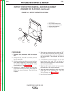
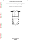
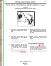
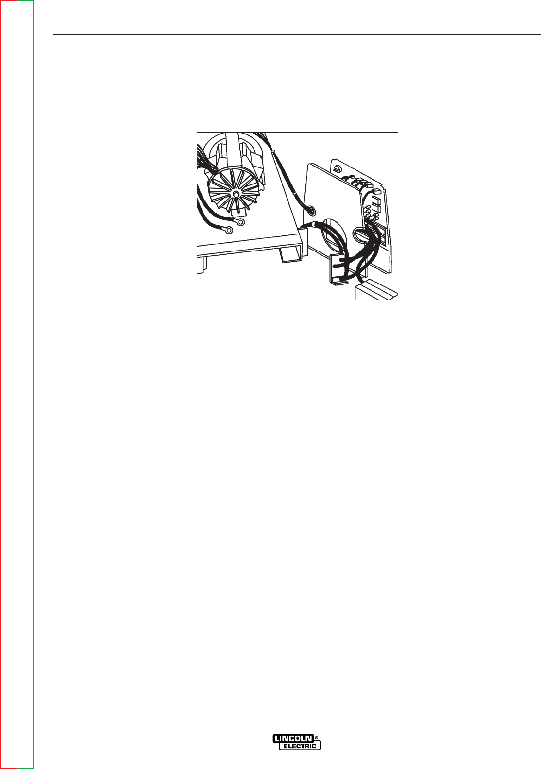
25. Carefully lift and pivot the front panel
assembly, along with the reactor, around to
the right side of the machine. See Figure
F.22. Support the unit with a box or large
pan.
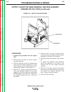
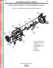
26. Remove the two 1/2” nuts and bolts that
hold the stator mounting bracket to the
base of the machine. See Figure F.21.
27. Remove the blower (fan) by turning it coun-
terclockwise to unscrew it from the rotor
shaft. Prevent engine rotation as you turn
the blower.
28. Remove the two 3/8” screws that hold the
rotor bearing in place.
29. Support the engine. Remove the eight
9/16” bolts that mount the stator to the
engine.
30. Using a gear puller, carefully remove the
stator.
ROTOR REMOVAL PROCEDURE
1. Support the rotor. See Figure F.21.
2. Using the 1/2” wrench, remove the six 1/2”
rotor bolts, lock washers, and three clamp-
ing bars. Caution: the rotor will be free to
fall when the bolts are removed.
3. Remove the rotor bearing. It must be
removed before the stator can be rein-
stalled.
FIGURE F.22
MACHINE FRONT COMPONENTS PIVOTED TO SIDE
STATOR AND/OR ROTOR REMOVAL AND REPLACEMENT (continued)