


Return to Section TOC Return to Section TOC Return to Section TOC Return to Section TOC
Return to Master TOC Return to Master TOC Return to Master TOC Return to Master TOC
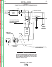
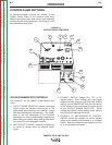
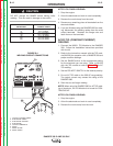
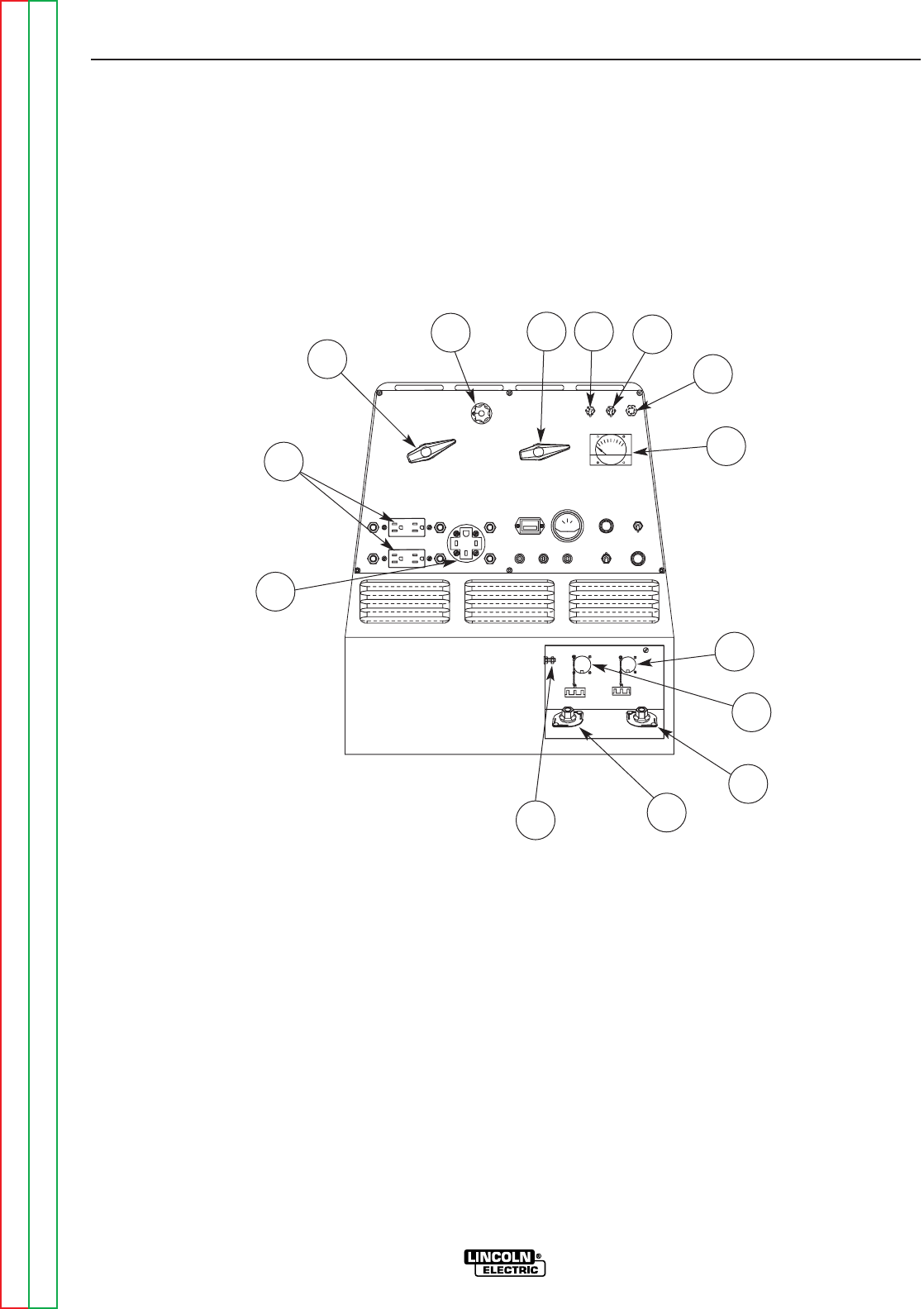
WELDER/GENERATOR CONTROLS
See Figure B.1 for the location of the following fea-
tures:
1. OUTPUT RANGE SELECTOR: Selects continuous
current output for constant current stick or TIG
applications (blue settings) and constant voltage
wire feed applications (red settings). The amper-
ages on the dial correspond to the maximum
amperages for each corresponding range setting.
Never change the range switch setting while weld-
ing, since this could damage the switch.
2. FINE OUTPUT CONTROL: Allows fine adjustment
of current or voltage within the selected output
range.
3. POLARITY SWITCH: Selects DC+, DC- or AC
welding output. Color codings aid in the proper
selection of stick (blue) or wire feed (red) polarity
setting. On the RANGER 300 DLX the color setting
of the polarity switch must match the color setting
of the OUTPUT RANGE SELECTOR. Never
change the polarity switch setting while welding
since this could damage the switch.
4. CONTROL AT WELDER/REMOTE CONTROL
SWITCH: Allows the operator to control welding
output at the welding control panel or at a remote
station. Remote connections are made at the 6 pin
or 14 pin amphenol connector.
OPERATION
B-5 B-5
RANGER 300 D AND 300 DLX
F
E
FIGURE B.1
OUTPUT PANEL CONTROLS
8
2
1
7
3 4
5
6
14
12
13
10
9
11
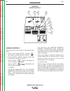
CONTROLS AND SETTINGS
All generator/welder controls are located on the
Output Control Panel of the machine case front.
Diesel engine glow plug, idler control, and start/stop
controls are also on the case front. See Figure B.1 and
the explanations that follow.