


HIGH FREQUENCY GENERATORS
FOR TIG APPLICATIONS
The K799 Hi-Freq Unit and the K930-1 or -2 TIG
Module can be used with the Ranger 300. The
machine is equipped with the required RF bypass cir-
cuitry for the connection of high frequency generating
equipment. The high frequency bypass network sup-
plied with the K799 Hi-Freq Unit does NOT need to be
installed into the Ranger 300.
The Ranger 300 and any high frequency generating
equipment must be properly grounded. See the K799
Hi-Freq Unit and the K930-1 TIG Module operating
manuals for complete instructions on installation,
operation, and maintenance. Also see the Acces-
sories section of this manual.
REMOTE CONTROL
The Ranger 300 DLX is equipped with a 6-pin and a
14-pin connector. The 6-pin connector is for connect-
ing the K857 or K857-1 Remote Control (optional) or
the K870 hand Amptrol or K812 foot Amptrol (TIG
applications).
The 14-pin connector is used to connect a wire feeder
or K930-1 TIG Module control cable. When a remote
output control is used, the output control toggle switch
must be set at REMOTE.
NOTE: When using the 14-pin connector, do NOT
connect anything to the 6-pin connector if the wire
feeder has a built-in power source output control.
Also see the Accessories section of this manual for
more information on wire feeder connections.
WELDING TERMINALS
The Ranger 300 DLX has a toggle switch for selecting
“hot” welding terminals (WELDING TERMINALS
ALWAYS ON position) or “cold” welding terminals
(WELDING TERMINALS REMOTELY CONTROLLED
position).
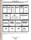
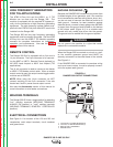
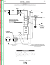
ELECTRICAL CONNECTIONS
See Figure A.1 for location of the 120 and 240 volt
receptacles, weld output terminals, circuit breakers
and ground stud.
MACHINE GROUNDING
Because the RANGER 300 creates its own power from
its diesel-engine driven generator, and if the machine
is not connected to premises wiring (home, shop, etc.),
you do not need to connect the machine frame to an
earth ground. However, for best protection against
electrical shock, connect a heavy gauge wire (#8 AWG
or larger) from the ground stud located on the bottom
of the output panel (Figure A.1) to a suitable earth
ground such as a metal pipe driven into the ground.
The ground stud is marked with the ground symbol.
Do not ground the machine to a pipe that carries
explosive or combustible material.
When the Ranger 300 is mounted on a truck or a trail-
er, the machine generator ground stud MUST be
securely connected to the metal frame of the vehicle.
See Figure A.1.
If the RANGER 300 is connected to premises wiring
such as a home or shop, it must be properly connect-
ed to the system earth ground.
INSTALLATION
A-6 A-6
RANGER 300 D AND 300 DLX
Return to Section TOC Return to Section TOC Return to Section TOC Return to Section TOC
Return to Master TOC Return to Master TOC Return to Master TOC Return to Master TOC
WARNING
F
E
2
1
4
3
1. 120/240 VOLT, 50 AMP RECEPTACLE
2. 120 VOLT, 15 AMP RECEPTACLES (2)
3. WELD OUTPUT TERMINALS
4. GROUND STUD
FIGURE A.1
RANGER 300 OUTPUT CONNECTIONS