


Return to Section TOC Return to Section TOC Return to Section TOC Return to Section TOC
Return to Master TOC Return to Master TOC Return to Master TOC Return to Master TOC
TROUBLESHOOTING & REPAIR
F-58 F-58
RANGER 300 D AND 300 DLX
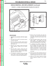
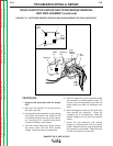
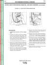
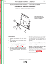
11. With the 1/4” nut driver, remove the
screws holding the control board.
12. Replace the old control board with a new
one.
13. Connect current sensing leads #254 and
#254A. Thread the leads through the cur-
rent sensor the same number of turns
noted during removal. Connect the leads
and install new wire ties. See the Wiring
Diagram for the proper connections.
14. Connect the three molex plugs.
15. Connect the three individual leads #213,
#222, and #5A.
16. Replace any wire ties that were cut during
the removal procedure.
17. With the 5/16” nut driver, install the control
board cover.
18. Install the case top, gaskets, and double
door support rod.
CONTROL BOARD REMOVAL AND REPLACEMENT (continued)