


Return to Section TOC Return to Section TOC Return to Section TOC Return to Section TOC
Return to Master TOC Return to Master TOC Return to Master TOC Return to Master TOC
TROUBLESHOOTING & REPAIR
F-36 F-36
RANGER 300 D AND 300 DLX
AUXILIARY AND FIELD WINDING TEST (continued)
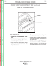
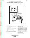
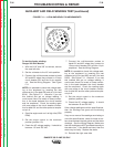
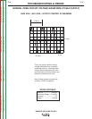
FIGURE F.11 – 14-PIN AMPHENOL PIN ASSIGNMENTS
To test the feeder winding:
Ranger 300 DLX Models
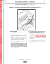
1. With the 5/16” and 3/8” nut drivers, remove
the case left side.
2. Set the voltmeter to the AC volts position.
3. Connect the volt/ohmmeter probes to leads
#31 and #32 where they connect to 15 amp
circuit breaker CB1 and the 14-pin amphe-
nol. See the Wiring Diagram. See Figure
F.11.
NOTE: It is possible to check this voltage read-
ing at the amphenol by inserting the test
probes at pin A (for lead #32) and pin J (for lead
#31A). See Figure F.11. However, if you use
this method and get no voltage reading, it
could mean there is a break or loose connec-
tion in the leads between the circuit breaker
and the amphenol. Check the reading again
with one probe at the circuit breaker connec-
tion for lead #31 and the other probe at amphe-
nol pin A.
4. Start the engine and run it at high idle (3700
RPM).
5. Set the output control to the maximum
position (position 10).
6. Check the AC voltage reading. It should be
between 115 and 126 VAC.
7. Connect the volt/ohmmeter probes to
leads #31 and #42 where they connect to
15 amp circuit breaker CB1 and the 14-pin
amphenol. See the Wiring Diagram.
NOTE: It is possible to check this voltage read-
ing at the amphenol by inserting the test
probes at pin K (for lead #42) and pin I (for lead
#31B). See Figure F.11. However, if you use
this method and get no voltage reading, it
could mean there is a break or loose connec-
tion in the leads between the circuit breaker
and the amphenol. Check the reading again
with one probe at the circuit breaker connec-
tion for lead #31 and the other probe at amphe-
nol pin K.
8. Set the output control to the maximum
position (position 10).
9. Check the AC voltage reading. It should
be between 43 and 50 VAC.
If the voltage readings are within specifications,
then the windings are good and functioning
properly.
If any one or more of the readings are missing or
not within specifications, check for loose or bro-
ken wires between the test points and the stator
windings. See the Wiring Diagram. Make sure
that the windings are NOT grounded internally to
the stator iron. If the leads are intact, then the
stator may be faulty. Replace the stator.
10. Reinstall the right case side.
K
B
I
H
N
L
C
D
M
G
E
F
J
A