


Return to Section TOC Return to Section TOC Return to Section TOC Return to Section TOC
Return to Master TOC Return to Master TOC Return to Master TOC Return to Master TOC
INSTALLATION
F-40 F-40
RANGER 300 D AND 300 DLX
CHARGING CIRCUIT TEST (continued)
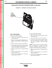
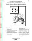
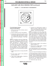
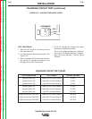
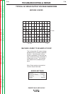
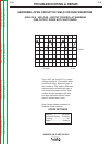
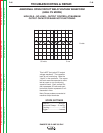
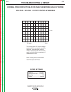
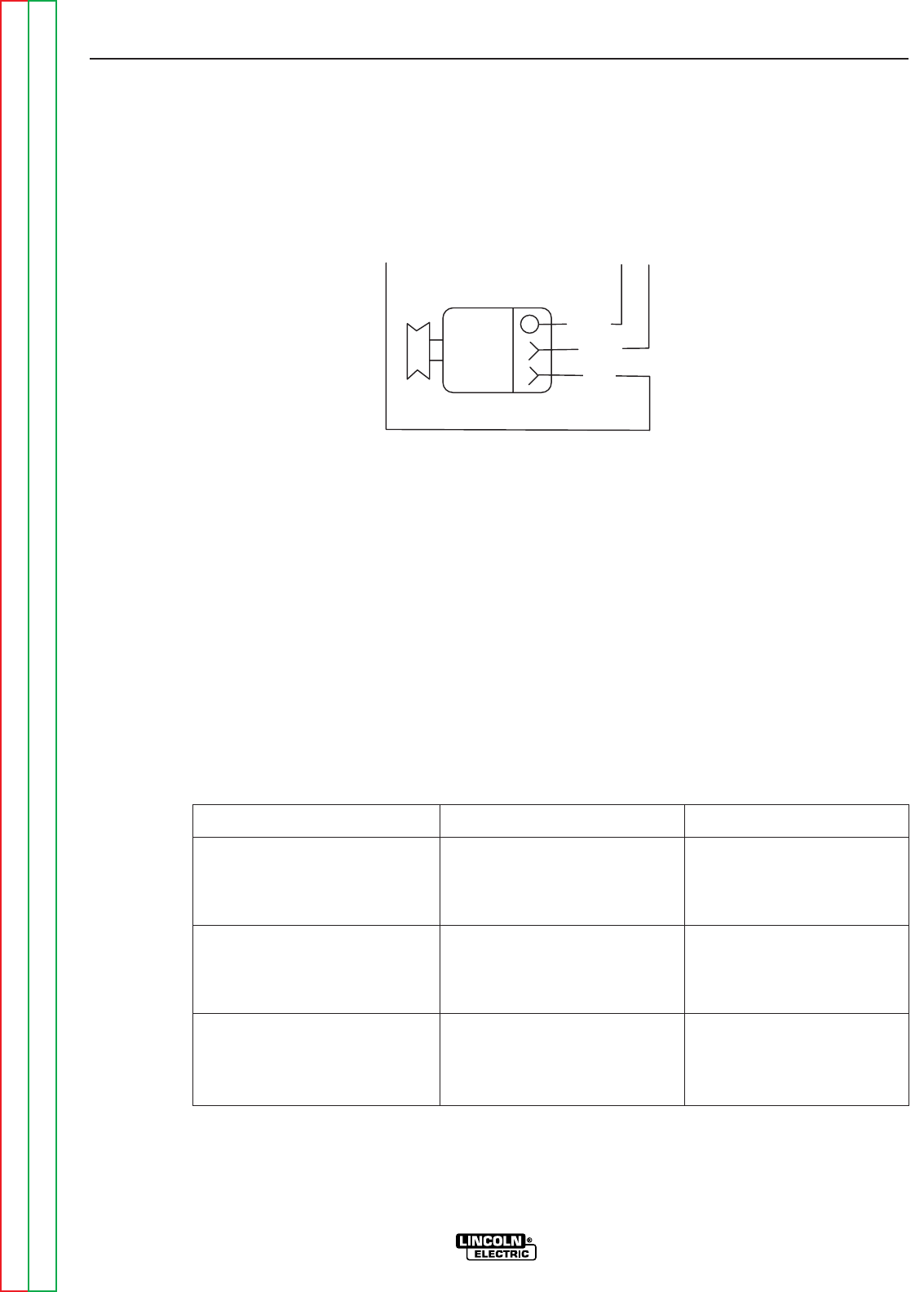
FIGURE F.13 – VOLTAGE REGULATOR LEADS
TEST PROCEDURE
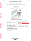
1. With the 5/16” and 3/8” nut drivers, remove
the right case side.
2. Locate the engine alternator and leads. See
Figure F.13.
3. Set the voltmeter for DC volts and check for
the typical DC voltages according to the
Charging Circuit Test Chart below.
4. If the DC voltages are correct, the engine
alternator is operating normally.
If any of the voltage readings are missing or
not normal, the engine alternator or associ-
ated wiring may be faulty. See the Wiring
Diagram.
CHARGING CIRCUIT TEST CHART
TEST CONDITIONS TEST POINTS TYPICAL VOLTAGE
Ignition Switch Off Lead 222D to Frame Ground 12 VDC
Ignition Switch Off Lead 224A to Frame Ground 0 VDC
Ignition Switch Off Lead 227 to Frame Ground 0 VDC
Ignition Switch On Lead 222D to Frame Ground 12 VDC
Ignition Switch On Lead 224A to Frame Ground 12 VDC
Ignition Switch On Lead 227 to Frame Ground 0.7 VDC
Engine running at 3700 RPM Lead 222D to Frame Ground 14.5 VDC
Engine running at 3700 RPM Lead 224A to Frame Ground 14.3 VDC
Engine running at 3700 RPM Lead 227 to Frame Ground 14.3 VDC
B
IG
L
222D
224A
ALTERNATOR
227