


Return to Master TOC Return to Master TOC Return to Master TOC Return to Master TOC
Section F-1 Section F-1
RANGER 300 D AND 300 DLX
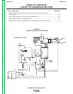
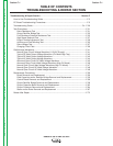
Troubleshooting & Repair Section .................................................................................Section F
How to Use Troubleshooting Guide ......................................................................................F-2
PC Board Troubleshooting Procedures.................................................................................F-3
Troubleshooting Guide.................................................................................................F4 - F-20
Test Procedures ...................................................................................................................F-21
Rotor Resistance Test ..................................................................................................F-21
Output Rectifier Bridge Test .........................................................................................F-23
Fuel Shutdown Solenoid Resistance Test ...................................................................F-25
High Speed Solenoid Test ............................................................................................F-27
Engine Throttle Adjustment Test ..................................................................................F-29
Auxiliary and Field Winding Test ...................................................................................F-33
Rotor Voltage Test ........................................................................................................F-37
Charging Circuit Test.....................................................................................................F-39
Oscilloscope Waveforms .....................................................................................................F-41
Normal Open Circuit Voltage Waveform (115 VAC Supply) .........................................F-41
Typical DC Weld Output Voltage Waveform (CV Mode High Tap) ................................F-42
Typical DC Weld Output Voltage Waveform..................................................................F-43
Typical AC Weld Output Voltage Waveform..................................................................F-44
Abnormal Open Circuit DC Weld Voltage Waveform....................................................F-45
Abnormal Open Circuit Weld Voltage Waveform (High CV Mode) ...............................F-46
Normal Open Circuit Weld Voltage Waveform (High CV Mode) ...................................F-47
Normal Open Circuit DC Weld Voltage Waveform .......................................................F-48
Normal Open Circuit AC Weld Voltage Waveform .......................................................F-49
Replacement Procedures ....................................................................................................F-50
Brush Removal and Replacement ...............................................................................F-50
Field Capacitor and/or Rectifier Bridge Removal and Replacement ...........................F-53
Control Board Removal and Replacement ..................................................................F-56
Output Rectifier Bridge Removal and Replacement.....................................................F-59
Output Capacitor Bank Removal and Replacement.....................................................F-62
Output Contactor Removal and Replacement..............................................................F-64
Stator and/or Rotor Removal and Replacement .........................................................F-67
Retest After Repair ..............................................................................................................F-72
TABLE OF CONTENTS
TROUBLESHOOTING & REPAIR SECTION