


Return to Section TOC Return to Section TOC Return to Section TOC Return to Section TOC
Return to Master TOC Return to Master TOC Return to Master TOC Return to Master TOC
TROUBLESHOOTING & REPAIR
F-22 F-22
RANGER 300 D AND 300 DLX
ROTOR RESISTANCE TEST (continued)
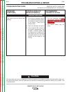
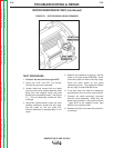
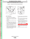
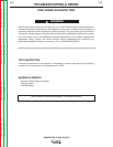
FIGURE F.1 – ROTOR BRUSH LEADS REMOVED
TEST PROCEDURE
1. Conduct the test with the engine OFF.
2. Using the 5/16” and 3/8” nut drivers,
remove the right front case side.
3. Locate, label and remove the two leads
from the rotor brush holder assembly (lead
#219 from the negative brush and lead
#220A from the positive brush). See Figure
F.1. This will electrically isolate the rotor
windings.
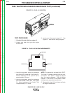
4. Using the volt/ohmmeter, check the rotor
winding resistance across the slip rings.
Set the meter on the low scale (X1).
Normal resistance is approximately 5 or 6
ohms.
5. Measure the resistance to ground. Set the
meter on the high scale (X100,000). Place
one meter probe on either of the slip rings.
Place the other probe on any good
unpainted ground. The resistance should
be very high, at least 500,000 ohms.
6. If the test does not meet the resistance
specifications, then the rotor may be faulty.
7. Connect the leads previously removed
from the brush assembly. Make sure the
leads are connected to the proper brushes
- lead #219 to the negative brush, lead
#200A to the positive brush.
8. Replace the right front case side previous-
ly removed.