


Return to Section TOC Return to Section TOC Return to Section TOC Return to Section TOC
Return to Master TOC Return to Master TOC Return to Master TOC Return to Master TOC
TROUBLESHOOTING & REPAIR
F-65 F-65
RANGER 300 D AND 300 DLX
OUTPUT CONTACTOR REMOVAL AND REPLACEMENT
(RANGER 300 DLX ONLY) (continued)
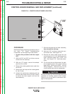
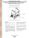
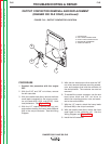
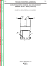
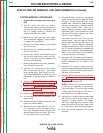
FIGURE F.19 – OUTPUT CONTACTOR LOCATION
PROCEDURE
1. Conduct this procedure with the engine
OFF.
2. With the 5/16” and 3/8” nut drivers, remove
the left case side.
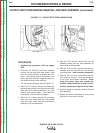
3. With the needle nose pliers, remove the three
small leads connected to the output contac-
tor coil (leads #232, #224, and #224C). Note
lead placement. See Figure F.20.
4. With the 1/2” wrench, remove the nut, bolt,
and washers holding the heavy leads (W8 and
W9) to the output contactor. See the Wiring
Diagram.
5. With the slot head screw driver and the 3/8”
nut driver, remove the three mounting screws,
nuts, and washers that hold the contactor to
the vertical baffle. The contactor can now be
removed.
6. To reinstall the output contactor, use the slot
head screw driver and 3/8” nut driver to
attach the mounting screws, nuts, and wash-
ers to the vertical baffle.
7. With the 1/2” wrench, attach the heavy leads
(W8 and W9) to the output contactor.
8. With the needle nose pliers, attach the three
small leads to the contactor coil. See the
Wiring Diagram and Figure F.20.
9. Install the left case side.
1. CONTACTOR
2. COIL LEAD CONNECTIONS
3. HEAVY LEAD CONNECTIONS
4. MOUNTING HARDWARE
5. VERTICAL BAFFLE
4
1
2
5
3