


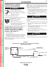
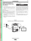
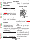

CONNECTION OF THE K930-1 TIG
MODULE TO THE RANGER 300 (DLX
ONLY) USING K936 CONTROL CABLE
(SEE FIGURE C.7.)
1. Shut the welder off.
2. Connect the electrode cable from the K930-1 TIG
Module to the ELECTRODE terminal of the welder.
Connect the work cable to the WORK terminal of
the welder.
NOTE: Welding cable must be sized for current and
duty cycle of application.
NOTE: Figure C.7 shows the electrode connected for
positive polarity. Use the Polarity switch on the Ranger
300 DLX to select the desired electrode polarity.
3. Connect the K936-1 Control Cable to the K930-1
TIG Module and to the 14-pin amphenol on the
Ranger 300 DLX.
4. Connect the K870 Foot Amptrol or K963-1 Hand
Amptrol or K814 Arc Start Switch to the K930-1
TIG Module.
5. Place the IDLER switch in the “AUTO” or “HIGH”
position as desired.
Any increase of the high idle engine RPM by changing
the governor setting or overriding the throttle linkage
will cause an increase in the AC auxiliary voltage. If
this voltage goes over 140 volts, wire feeder control
circuits may be damaged. The engine governor set-
ting is preset at the factory - do not adjust above RPM
specifications listed in this manual.
6. Set the LOCAL/REMOTE switch to “REMOTE.”
7. Set the OUTPUT RANGE switch to “STICK WELD-
ING.”
8. Set the WELDING TERMINALS switch to “WELD-
ING TERMINALS REMOTELY CONTROLLED.”
ACCESSORIES
C-9 C-9
RANGER 300 D and 300 DLX
Return to Section TOC Return to Section TOC Return to Section TOC Return to Section TOC
Return to Master TOC Return to Master TOC Return to Master TOC Return to Master TOC
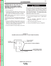
FIGURE C.7
RANGER 300 DLX/K930-1 TIG MODULE CONNECTION DIAGRAM
14 PIN
AMPHENOL
ELECTRODE
K963-1 HAND AMPTROL
-OR-
-OR-
K814 ARC START SWITCH
K870 FOOT AMPTROL
FLOWMETER
K936-1
CONTROL CABLE
INPUT
REGULATOR
TO GAS
FITTING
CYLINDER
ARGON GAS
TO WORK
CAUTION