


Return to Section TOC Return to Section TOC Return to Section TOC Return to Section TOC
Return to Master TOC Return to Master TOC Return to Master TOC Return to Master TOC
TROUBLESHOOTING & REPAIR
F-32 F-32
RANGER 300 D AND 300 DLX
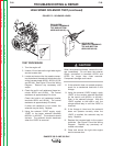
ENGINE THROTTLE ADJUSTMENT TEST (continued)
6. If either of the readings is incorrect, adjust
the throttle as follows:
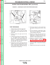
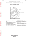
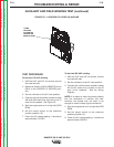
Adjust HIGH IDLE: First make sure there is
NOT a load on the machine. Set the IDLER
switch to the HIGH position. The solenoid
should activate. Using the 7/16” wrench,
adjust the high speed solenoid linkage to
lengthen the linkage until the engine speed
starts to decrease. See Figure F.7. Adjust
the linkage in the opposite direction until
the engine speed is within limits (3650 -
3700 RPM). Tighten the locking nut. The
high speed set screw is preset and sealed
by the engine manufacturer and normally
should not be adjusted.
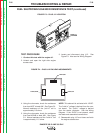
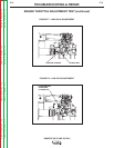
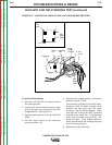
Adjust LOW IDLE: First make sure there is
NOT a load on the machine. Set the IDLER
switch to AUTO and wait for the engine to
change to low idle speed. Use the 10mm
wrench to loosen the lock nut on the low
speed set screw. See Figure F.8. Adjust
the set screw until the engine speed is
between 2150 and 2220 RPM. Tighten the
lock nut.
Fr
equency Counter Method
1. Plug the frequency counter into one of the
115 VAC receptacles.
2. Start the engine and check the frequency
counter. At HIGH IDLE (3700 RPM), the
counter should read 63 Hz. At LOW IDLE
(2220 RPM), the counter should read 37 Hz.
Note that these are median measurements;
Hertz readings may vary slightly above or
below.
3. If either of the readings is incorrect, adjust
the throttle as follows:
Adjust HIGH IDLE: First make sure there is
NOT a load on the machine. Set the IDLER
switch to the HIGH position. The solenoid
should activate. Using the 7/16” wrench,
adjust the high speed solenoid linkage to
lengthen the linkage until the engine speed
starts to decrease. See Figure F.7. Adjust
the linkage in the opposite direction until
the frequency is 63 Hz. Tighten the locking
nut. The high speed set screw is preset and
sealed by the engine manufacturer and nor-
mally should not be adjusted.
Adjust LOW IDLE: First make sure there is
NOT a load on the machine. Set the IDLER
switch to AUTO and wait for the engine to
change to low idle speed. Use the 10mm
wrench to loosen the lock nut on the low
speed set screw. See Figure F.8. Adjust
the set screw until the frequency is 37 Hz.
Tighten the lock nut.
Oscilloscope Method
1. Connect the oscilloscope to the 115 VAC
receptacle, according to the manufacturer’s
instructions. At HIGH IDLE (3700 RPM), the
waveform should exhibit a period of 15.8
milliseconds. At LOW IDLE (2220 RPM), the
waveform should exhibit a period of 27.02
milliseconds. Refer to the NORMAL OPEN
CIRCUIT VOLTAGE WAVEFORM (115VAC
SUPPLY) HIGH IDLE - NO LOAD in this
section of the manual.
2. If either of these waveform periods is incor-
rect, adjust the throttle as follows:
Adjust HIGH IDLE: First make sure there is
NOT a load on the machine. Set the IDLER
switch to the HIGH position. The solenoid
should activate. Using the 7/16” wrench,
adjust the high speed solenoid linkage to
lengthen the linkage until the engine speed
starts to decrease. See Figure F.7. Adjust
the linkage in the opposite direction until
the period is 15.8 milliseconds. Tighten the
locking nut. The high speed set screw is
preset and sealed by the engine manufac-
turer and normally should not be adjusted.
Adjust LOW IDLE: First make sure there is
NOT a load on the machine. Set the IDLER
switch to AUTO and wait for the engine to
change to low idle speed. Use the 10mm
wrench to loosen the lock nut on the low
speed set screw. See Figure F.8. Adjust
the set screw until the period is 27.02 mil-
liseconds. Tighten the lock nut.