


Return to Section TOC Return to Section TOC Return to Section TOC Return to Section TOC
Return to Master TOC Return to Master TOC Return to Master TOC Return to Master TOC
TEST PROCEDURE
1. Conduct this test with the engine off.
2. Unlatch and open the right side engine
access door.
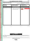
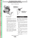
3. Locate and disconnect plug J12. See
Figure F.3. Also see the Wiring Diagram.
TROUBLESHOOTING & REPAIR
F-26 F-26
RANGER 300 D AND 300 DLX
FUEL SHUTDOWN SOLENOID RESISTANCE TEST (continued)
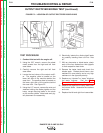
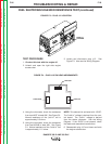
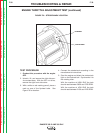
FIGURE F.3 – PLUG J12 LOCATION
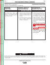
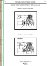
FIGURE F.4 – PLUG J12 PIN/LEAD ASSIGNMENTS
LEAD #237
LEAD #224B
LEAD #5K
4. Using the ohmmeter, check the resistance
from lead #237 to lead #5K. See Figure F.4.
Normal resistance of the “pull-in” coil is
approximately 0.5 ohms.
5. Using the ohmmeter, check the resistance
from lead #224B to lead #5K. See Figure
F.4. Normal resistance of the “hold-in” coil
is approximately 11.5 ohms.
NOTE: This solenoid is activated with 12VDC.
The “hold-in” voltage is derived from the con-
trol board. The “pull-in” voltage is derived
from the starter contactor. See the Wiring
Diagram. If the 12VDC is not present, check
the leads and associated connections.
6. Reassemble plug J12 and close and latch
the engine access door.
PLUG J12
LOCATION