


TROUBLESHOOTING & REPAIR
F-30 F-30
RANGER 300 D AND 300 DLX
Return to Section TOC Return to Section TOC Return to Section TOC Return to Section TOC
Return to Master TOC Return to Master TOC Return to Master TOC Return to Master TOC
ENGINE THROTTLE ADJUSTMENT TEST (continued)
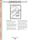
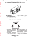
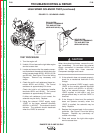
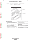
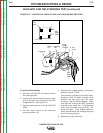
FIGURE F.6 – STROBE MARK LOCATION
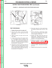
TEST PROCEDURE
1. Conduct this procedure with the engine
OFF.
2. Unlatch, lift, and secure the right side ser-
vice access door. With the 3/8” nut driver,
remove the right front side cover.
3. With a white or red marking pencil, place a
mark on one of the flywheel bolts. See
Figure F.6 for location.
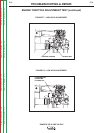
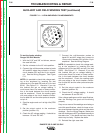
4. Connect the strobe-tach according to the
manufacturer’s instructions.
5. Start the engine and direct the strobe-tach
light on the flywheel bolt. Synchronize it to
the rotating mark.
With the machine at HIGH IDLE the tach
should read between 3650 and 3700 RPM.
With the machine at LOW IDLE the tach
should read between 2150 and 2220 RPM.
FLYWHEEL
CHALK MARK