


Return to Section TOC Return to Section TOC Return to Section TOC Return to Section TOC
Return to Master TOC Return to Master TOC Return to Master TOC Return to Master TOC
TROUBLESHOOTING & REPAIR
F-60 F-60
RANGER 300 D AND 300 DLX
OUTPUT RECTIFIER BRIDGE REMOVAL AND REPLACEMENT (continued)
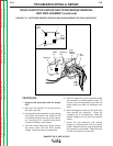
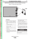
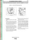
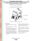
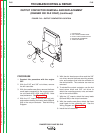
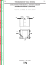
FIGURE F.17 – OUTPUT RECTIFIER CONNECTIONS
PROCEDURE
1. Conduct this procedure with the engine
OFF.
2. With the 5/16” and 3/8” nut drivers, carefully
remove the left and right case sides. Note
that the output rectifier is divided into two
parts. The positive portion is located on the
lower right side and the negative portion on
the lower left side of the machine.
For the remaining steps, refer to Figure F.17.
3. With the 1/2” wrench, remove the diode pig-
tails and heavy leads from the terminal studs.
Note lead and washer placement: nut, split
washer, flat washer, leads. Label leads for
reassembly. See the Wiring Diagram.
4. With the 1/2” wrench, remove the two heavy
leads and one small lead from the rectifier
heat sink plate. Note that the small lead is
always on top for reassembly.
5. With the 7/16” wrench, remove the nut and
washers holding the top stud assembly to
the rectifier mounting bolts.
6. With the 7/16” wrench, remove the nuts, lock
washers, and flat washers from the two top
mounting bolts. Note insulator placement.
7. With the 3/8” nut driver, remove the two bot-
tom mounting screws. Note the placement
of the nylon and Nomex insulators. These
must be in place when you reinstall the
rectifier bridge assembly in order to elec-
trically insulate the bridge from the frame.
8. Clear the leads and carefully remove the heat
sink assembly.
9. Repeat the above procedure to remove the
other half of the output rectifier.
Left Side (–) Right Side (+)