


Return to Section TOC Return to Section TOC Return to Section TOC Return to Section TOC
Return to Master TOC Return to Master TOC Return to Master TOC Return to Master TOC
TROUBLESHOOTING & REPAIR
F-38 F-38
RANGER 300 D AND 300 DLX
ROTOR VOLTAGE TEST (continued)
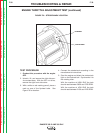
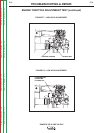
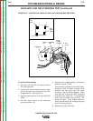
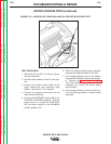
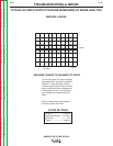
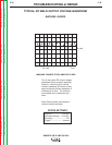
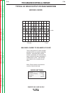
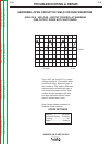
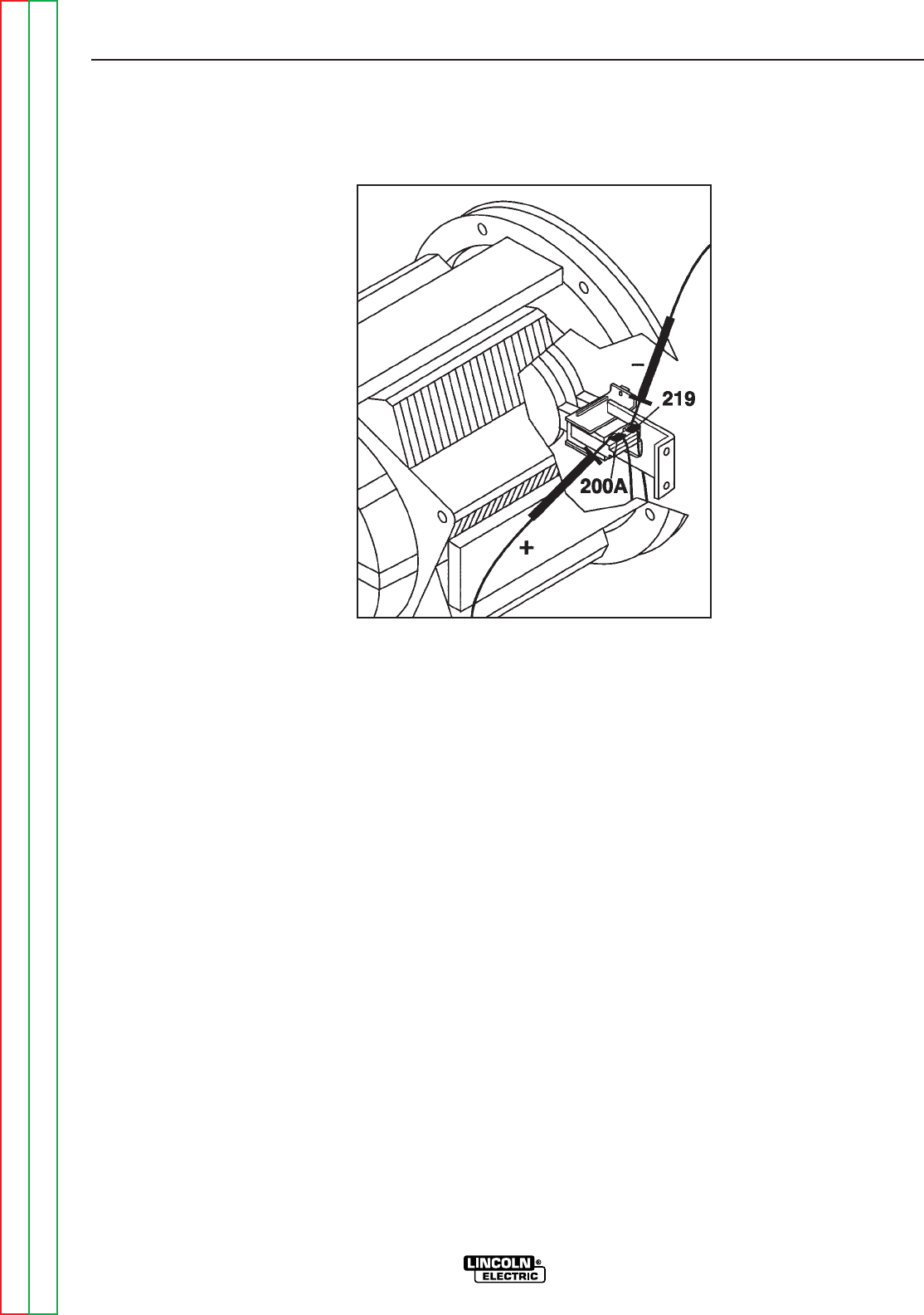
FIGURE F.12 – LOCATION OF LEADS 200A AND 219 FOR ROTOR VOLTAGE TEST
TEST PROCEDURE
1. With the 5/16” and 3/8” nut drivers, remove
the right case side.
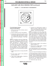
2. Set the volt/ohmmeter to the DC volts posi-
tion.
3. Connect the positive meter probe to the
brush nearest the rotor lamination (lead
#200A). See Figure F.12 for location.
4. Connect the negative meter probe to the
other brush (lead #219).
5. Set the LOCAL/REMOTE switch (S8) to the
CONTROL AT WELDER position. Start the
engine and run it at high idle (3700 RPM).
Set the output control to the MAXIMUM
position (position 10).
6. Check the voltage reading on the voltmeter.
It should read approximately 37-40 VDC.
7. If the voltage reading is low or not present,
the generator field is not functioning proper-
ly. Perform the Rotor Resistance Test.
The Field Diode Bridge (D2), the Field
Capacitor (C1), and/or the control board
may be faulty.
8. If the voltage reading is normal, the field cir-
cuit is functioning properly. Install the right
case side.