


Return to Section TOC Return to Section TOC Return to Section TOC Return to Section TOC
Return to Master TOC Return to Master TOC Return to Master TOC Return to Master TOC
TROUBLESHOOTING & REPAIR
F-28 F-28
RANGER 300 D AND 300 DLX
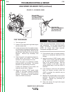
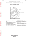
HIGH SPEED SOLENOID TEST (continued)
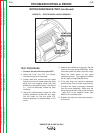
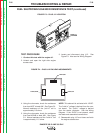
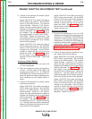
FIGURE F.5 – SOLENOID LEADS
PULL-IN COIL
(LARGER TERMINALS
TOP AND BOTTOM
#222H AND #213A)
HOLD-IN COIL
(SMALLER TERMINALS
TOP AND BOTTOM
#222J AND #214A)
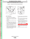
TEST PROCEDURE
1. Turn the engine off.
2. Unlatch, lift and secure the right side engine
service access door.
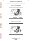
3. Locate and remove the four spade connec-
tors that attach the solenoid terminals to the
wiring harness leads (#222J, #222H, #213A
and #214A). See Figure F.5 and the Wiring
Diagram. Remove any necessary wire
wraps.
4. Check the pull-in coil resistance (larger ter-
minals #222H and #213A). The normal
resistance is approximately 0.4 ohms.
Check the hold-in coil resistance (smaller
terminals #222J and #214A). The normal
resistance is approximately 20 ohms).
If either coil resistance is not correct, the
solenoid may be faulty. Replace.
5. Using the external 12VDC supply, apply
12VDC to the larger solenoid terminals
(#222H+ to #213A-). The solenoid should
activate. The solenoid should deactivate
when the 12VDC is removed.
When the solenoid activates, remove the volt-
age immediately. Do not leave the external
supply connected to terminals #222H and
#213A for longer than three seconds.
Component damage could result.
8. If the solenoid does not operate properly,
check for a mechanical restriction in the
linkage.
9. Using the external 12VDC supply, apply
12VDC to the smaller solenoid terminals
for the hold-in coil (#222J+ to #214A-).
Push in the solenoid plunger. With the
12VDC applied to the hold-in coil, the
plunger should stay in until the 12VDC is
removed.
10. If the linkage is intact and the solenoid
does not operate correctly when the
12VDC is applied, the solenoid may be
faulty. Replace.
11. Replace the harness leads to the correct
terminals. See Figure F.5 and the Wiring
Diagram. Replace any previously re-
moved wire wraps.
12. Close and secure the right side engine
service access door.
CAUTION