


Return to Section TOC Return to Section TOC Return to Section TOC Return to Section TOC
Return to Master TOC Return to Master TOC Return to Master TOC Return to Master TOC
TROUBLESHOOTING & REPAIR
F-57 F-57
RANGER 300 D AND 300 DLX
CONTROL BOARD REMOVAL AND REPLACEMENT (continued)
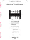
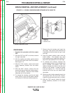
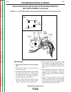
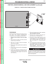
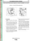
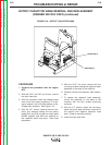
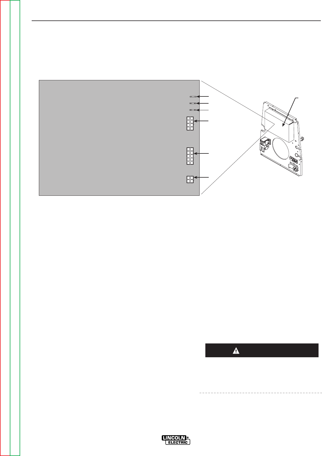
FIGURE F.16 – PRINTED CIRCUIT BOARD LOCATION
PROCEDURE
Before starting the following procedure, refer to
the topic “PC Board Troubleshooting
Procedures” at the beginning of this section.
1. Conduct this procedure with the engine
OFF.
2. With the 5/16” and 3/8” nut drivers, remove
screws from the case top.
3. With the 1/2” wrench, remove the exhaust
pipe from the muffler.
4. Remove the rubber gasket (cover seal) from
the lift bail.
5. Remove the fuel cap and the rubber gasket
for the fill tube.
6. Unlatch the double door assembly and use
the slot head screw driver and 3/8” wrench
to remove the door support rod from the
door assembly.
7. Remove the case top and door assembly,
then reinstall the fuel cap.
8. With the 5/16” nut driver, remove the con-
trol board cover. See Figure F.16.
9. Remove the three molex plugs from the
control board (J1, J2, J3). Also remove the
three individual leads #213, #222, and
#5A. See Figure F.16. Note lead place-
ment.
10. Cut the wire ties and disconnect the bolt-
ed connections from the current sensing
leads (#254, #254A and #254B - see the
Wiring Diagram). Count the turns in the
current sensor and note for reassembly.
Be sure to follow the recommended static-free
methods for handling printed circuit boards.
Failure to do so can result in permanent dam-
age to the equipment.
CONTROL
B213
B5A
B222
J1
J2
J3
CONTROL
BOARD
COVER
CAUTION