


3-91
Mode changeover switch input
3 Controller
3.7 Mode changeover switch input
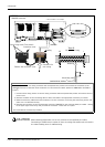
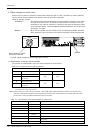
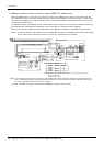
Connect the key switch of customer prepared and change the right of robot’s operation by switch operation.
The key switch can be installed in the operation panel of customer preparation.
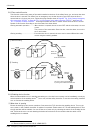
<Right of operation (mode)>
AUTOMATIC.......................The operation from external equipment becomes available. Operation which needs
the right of operation from T/B cannot be performed. It is necessary to set the
parameter for the rights of operation to connection with external equipment. Refer
to the separate volume, "Instruction Manual/Detailed Explanation of Functions and
Operations" for detail.
MANUAL ..............................When T/B is available, only the operation from T/B becomes available. Operation
which needs the right of operation from external equipment cannot be performed.
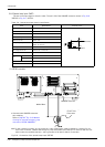
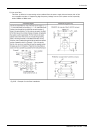
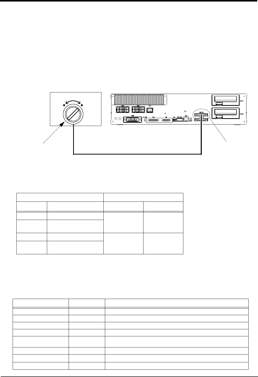
Fig.3-20 : Mode changeover switch image figure (CR751)
(1) Specification of the key switch interface
The function and specification of the key switch interface are shown below.
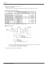
Table 3-7 : Specification of the mode changeover switch input
Item Specification Remarks
Rated voltage DC24V Supply from the controller.
Current rating Approx. 10mA Select the switch or button which operates normally in 24V/10mA.
Input resistance Approx. 2.2kΩ
Response time (OFF->ON) Approx. 15ms Example: The response time the program starts, after pushing the run button.
Common method 1 point per
common
Connection method Connector
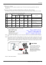
Conformity electric wire size AWG#24 to #18
0.2 to 0.75mm
2
Maker/Type - Maker: PHOENIX CONTACT/ Type: FKC2.5/4-STF-5.0B
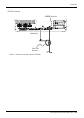
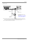
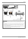
MODE
MANUAL AUTOMATIC
Mode changeover switch
(Customer-prepared)
CNUSR1
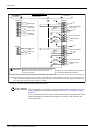
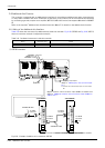
Table 3-6 : Function of the key switch interface
Pin number and Function (Connector: CNUSR1)
Change mode
Note1)
Note1) The mode changes by both opening or both closing between 30-5 pin and between 35-10
pin. Maintain the current mode except it.
Pin number Function MANUAL AUTOMATIC
49 1st line KEY input
Open Close
24 Power supply +24V of pin
number 49
50 2nd line KEY input
Open Close
25 Power supply +24V of pin
number 50
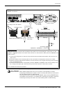
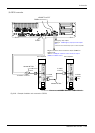
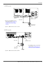
[Note] In the customer's system, do not ground the + side of 24V power supply prepared by customer for connect to the
controller. (related with emergency stop and parallel input/output) If it connects with the controller under the condi
-
tion that the + side is grounded, it will lead to failure of controller.