


3-109
External I/O cable
3 Controller
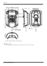
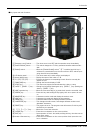
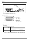
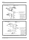
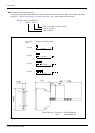
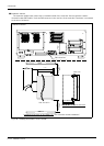
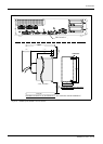
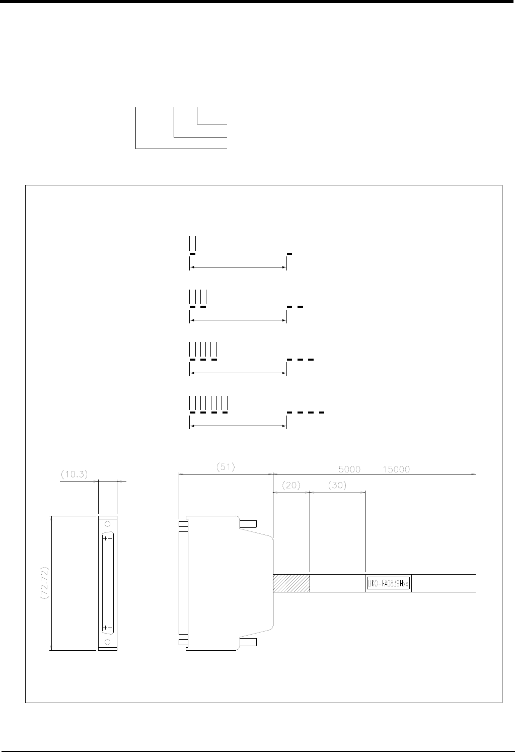
■ Connections and outside dimensions
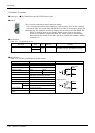
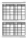
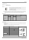
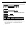
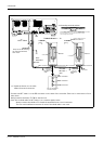
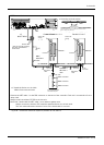
The sheath of each signal cable (40 lines) is color indicated and marked with dots. Refer to the cable color speci
-
fications in "Table 3-32: Connector pin numbers and cable colors" when making the connections.
Fig.3-34 : Connections and outside dimensions
(Eg.) Pin number: color indication
1 : Orange / Red / a
Type of dot mark (see figure below)
Color of dot mark
Color of sheath
Line color
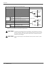
type
a type
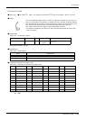
Pattern of the print mark
One dot
Two dots
Three dots
Four dots
b type
c type
d type
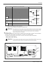
1A/C 1B/D
20A/C
20B/D
or
Plug (Fujitsu Ltd) Connector : FCN-361J040-AU
Cover : FCN-360C040-B