3 Controller
Emergency stop input and output etc.
3-80
Make sure there are no mistakes in the wiring. Connecting differently to the way
specified in the manual can result in errors, such as the emergency stop not being
released. In order to prevent errors occurring, please be sure to check that all functions
(such as the teaching box emergency stop, customer emergency stop, and door switch)
are working properly after the wiring setup is completed.
You should always connect doubly connection of the emergency stop, the door switch,
and the enabling switch. In connection of only one side, if the relay of customer use
should break down, it may not function correctly.
And, the output contacts from the robot controller (robot error output, emergency stop
output, mode output, addition axis contactor control output) are dual contacts (syn
-
chronizes). You should connect surely by dual line with the customer's equipment as
well as connection of the emergency stop and the door switch.
Please make sure to wire the multiple emergency stop switches so that they each
function independently. Check and make sure that the emergency stop doesn't only
function under an AND condition (when multiple emergency stop switches are ON at
the same time).
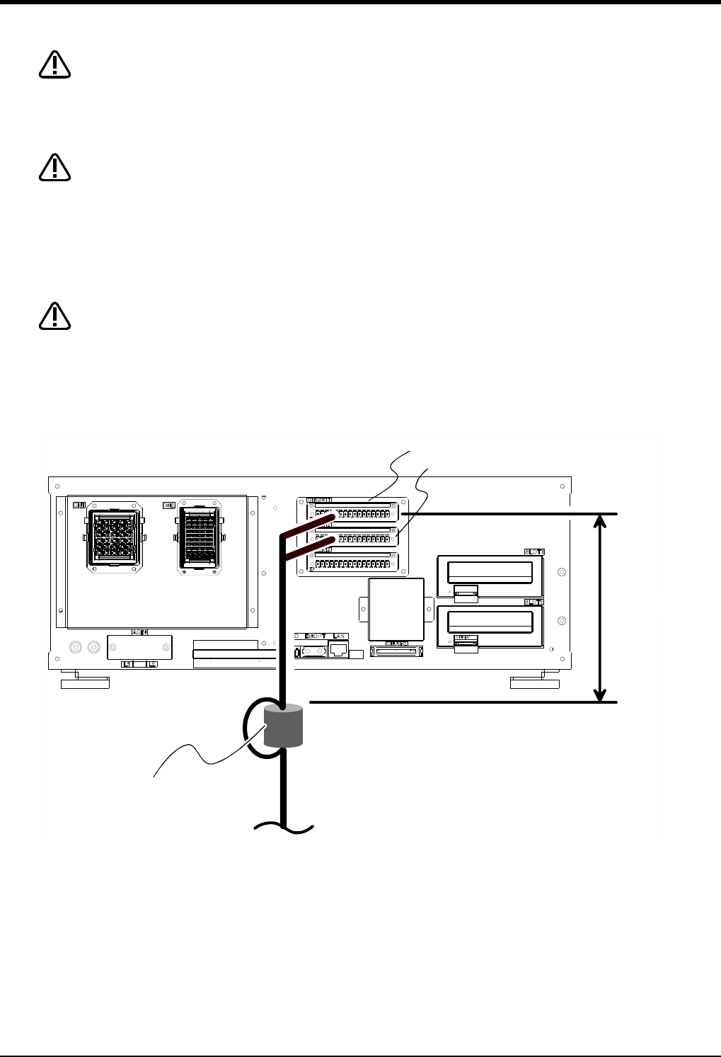
(1) CR750 controller
Fig.3-9 : Emergency stop cable connection (CR750)
CAUTION
CAUTION
CAUTION
30cm以内
フェライトコア
2回通し
CNUSR11コネクタ
CNUSR12コネクタ
CNUSR11 connector
Within 30 cm
Ferrite core
Pass twice
CNUSR12 connector


