


3-83
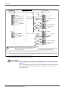
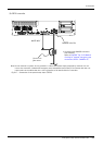
Emergency stop input and output etc.
3 Controller
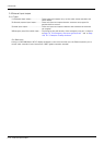
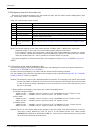
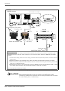
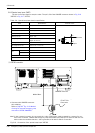
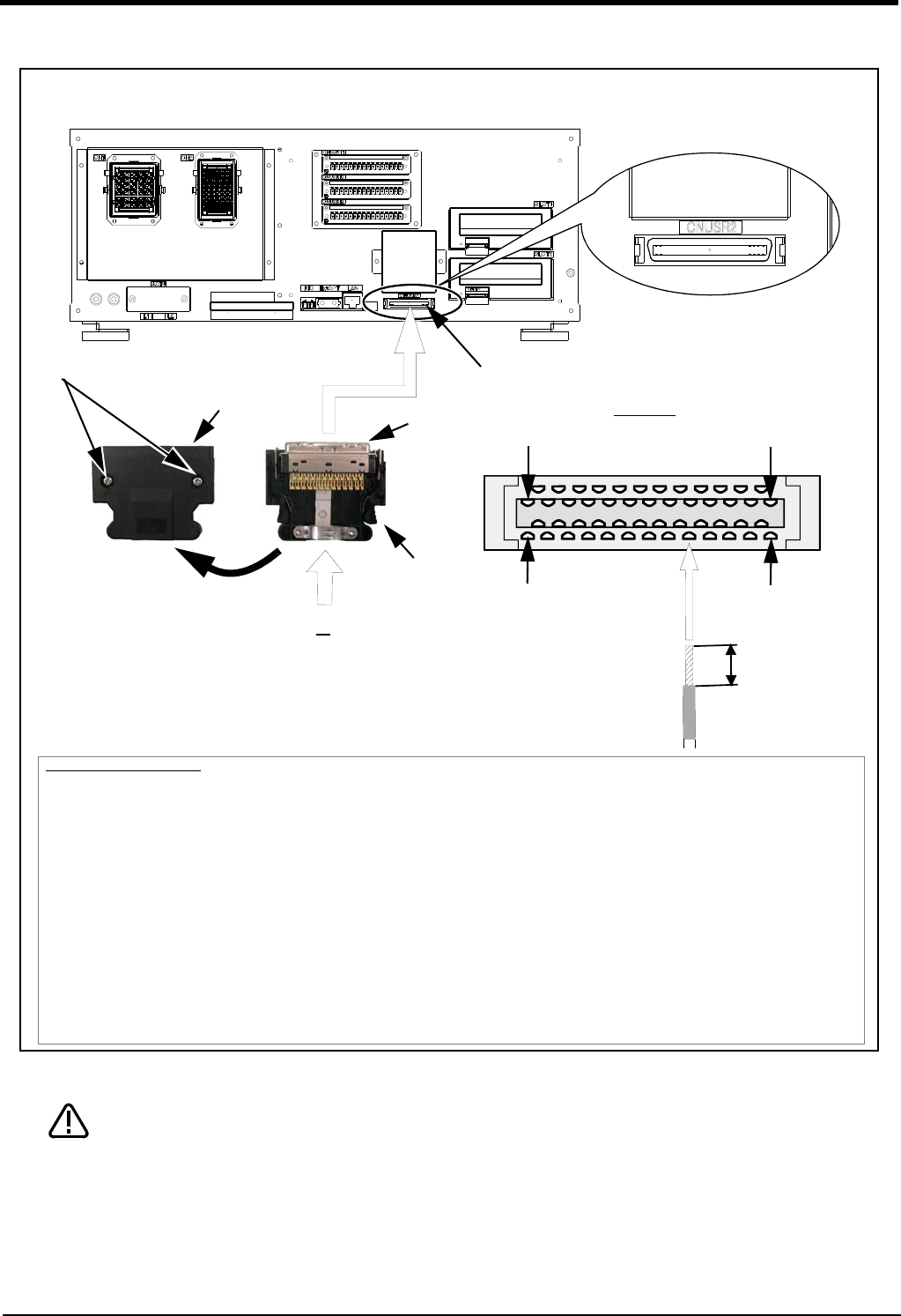
Fig.3-12 : Method of wiring for external emergency stop connection (CR750 (CNUSR2))
When soldering please take care to only connect to the specified pin number.
Connecting to a different pin number or short-circuiting with another pin will result in
the robot breaking down or malfunctioning.
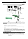
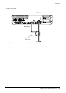
<CR750 controller>
CNUSR2 connector
CNUSR2
3mm
A
View A
Plug
Connector cover
Connecting cable
(AWG #30-24 (0.05mm
2
-0.2mm
2
))
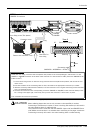
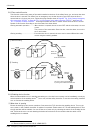
Connection procedure
Solder the pins of the user wiring connector that accompanies the product, and connect the connector to the
CNUSR2 connector at the back of the controller. For the connection cables, please use AWG #30 to 24 (0.05 to
0.2mm
2
).
1) Loosen the two fixing screws on the user wiring connector that accompanies the product, and remove the con
-
nector cover.
2) Peel the insulation of the connecting cable to 3mm, and solder it the appropriate connector pin number.
3) After the necessary cables have been soldered, re-fix the connector cover using the same fixing screws and
make sure it is fastened securely.
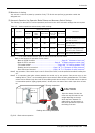
4) Connect the connector to the corresponding connector (CNUSR2) on the controller. With pin number 1 facing
to the upper right, insert firmly until you hear the connector’s latch click in to place.
This concludes the connection procedure.
Cover fixing screw (Two places)
Remove the connector cover
Pin number of plug
25
1
50
26
Soldering
Connector for
user wiring
* The controller is an example.
CAUTION