


1-5
1 General configuration
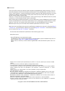
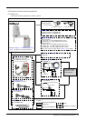
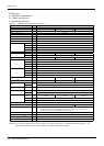
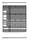
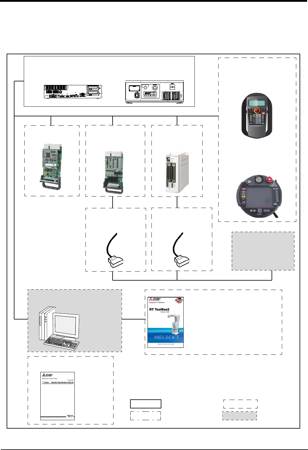
1.6.2 Controller
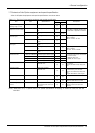
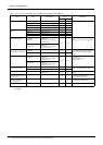
The devices shown below can be installed on the controller.
The controllers that can be connected differ depending on the specification of the robot. (Refer to Page 2, "1.2
Model type name of robot".)
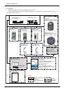
Fig.1-2 : Structural equipment
Personal computer
Prepared by customer
*)Refer to Table
1-5 for USB
cable
Instruction Manual (bookbinding)
・ 5F-FA01-PE01
Parallel I/O interface
2D-TZ368(Sink)/
2D-TZ378(Source)
CC-Link interface
2D-TZ576
Teaching pendant (T/B)
Simple T/B
・ R32TB: For CR750 controller
・ R33TB: For CR751 controller
Highly efficient T/B
・ R56TB: For CR750 controller
・ R57TB: For CR751 controller
Controller
・ CR751-03HD-0
・ CR751-03HD1-0-S15
・ CR750-03HD1-1-S15
External I/O cable
・ 2D-CBL05 (5m)
・ 2D-CBL15 (15m)
Parallel I/O unit
2A-RZ361(Sink)/
2A-RZ371(Source)
External I/O cable
・ 2A-CBL05 (5m)
・ 2A-CBL15 (15m)
RT ToolBox2/RT ToolBox2 mini
RT ToolBox2
・ 3D-11C-WINE(CD-ROM)
(Windows XP、 Windows Vista、 Windows 7、
Windows 8、 Windows 8.1)
RT ToolBox2 mini
・ 3D-12C-WINE(CD-ROM)
(Windows XP、 Windows Vista、 Windows 7、
Windows 8、 Windows 8.1)
PLC (Programmable
Logic Controller)
External device
Prepared by customer
Standard configuration
Special specifications
Options
Prepared by
[Caution]
equipment
customer