


3 Controller
Parallel I/O unit
3-112
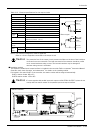
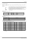
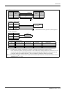
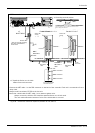
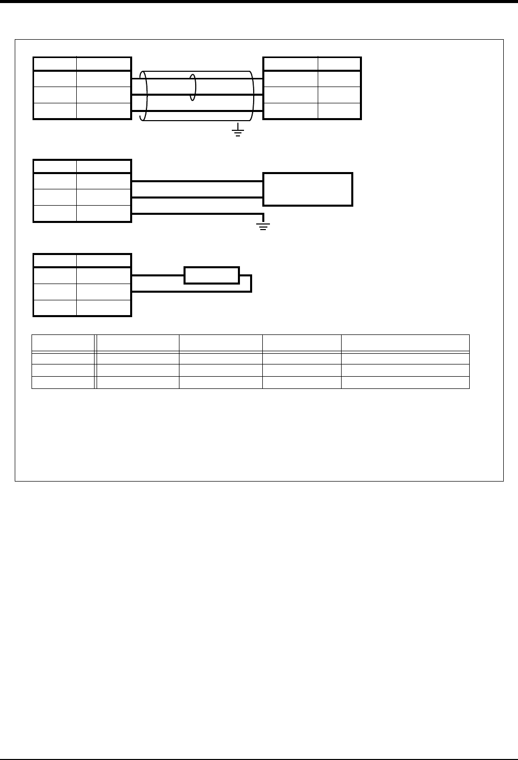
Fig.3-35 : Specifications for the connection cable
NETcable-1 (Network cable)
Pin No. RIO1/2 RIO1/2 Pin No.
1TXRXH TXRXH1
2 TXRXL TXRXL 2
3 SG(GND) SG(GND) 3
FG
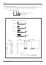
DCcable-2 (Power cable)
Pin No. DCIN
1 24V +
24V Power
224G -
3FG(PE)
Connected the frame ground or protect ground
R-TM (Terminator)
Pin No. RIO1/2 100Ω
1TXRXH
2 TXRXL
3 SG(GND)
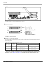
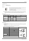
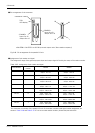
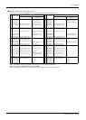
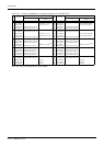
List of parts and manufacturer
Type Connector type Contact type Resistant Manufacturer
NETcable-1 51103-0300 (1) 50351-8100 (3) - MOLEX (White connector)
DCcable-2 2-178288-3 (1) 175218-3 (3) - Tyco Electronics (Black connector)
R-TM 1-178288-3 (1) 175218-3 (2) 100Ω(1/4W) (1) Equivalent to KOA.
Note 2)
Note 1)
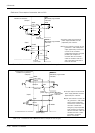
Note 1) The 24V power supply is prepared by customer (The power consumption is approx. 0.3A.)
In the customer's system, do not ground the + side of 24V power supply prepared by customer for con
-
nect to the controller. (related with emergency stop and parallel input/output) If it connects with the
controller under the condition that the + side is grounded, it will lead to failure of controller.
Note 2) The cable for general purpose can be used to the network cable. However, use the twisted shield cable of
AWG#22(0.3mm
2
) or more.