


3 Controller
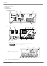
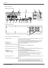
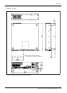
Names of each part
3-66
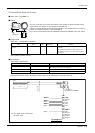
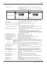
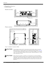
<1> ACIN terminal................................................The terminal box for AC power source (single phase, AC200V) input.
(Inner side of a cover)
There are two types of the terminal and the terminal differs depending
on the specification (CE or non-CE).
Refer to a separate manual “INSTRUCTION MANUAL/Controller setup,
basic operation, and maintenance” for how to connect a power cable.
<2> PE terminal.....................................................The screw for grounding of the cable. (M4 screw x 2 place)
<3> Power switch .................................................This turns the control power ON/OFF
<4>
Machine cable connector (motor signal) (CN1)
Connect with the CN1 connector of the robot arm.
<5>
Machine cable connector (motor power) (CN2)
Connect with the CN2 connector of the robot arm.
<6> T/B connection connector (TB) ...........This is a dedicated connector for connecting the T/B. When not using T/
B, connect the attached dummy connector.
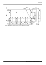
<7><8><9><10> CNUSR connector ..............The connector for input/ output connection dedicated for robot. (a plug
connector attached)
<7>: CNUSR11, <8>: CNUSR12, <9>: CNUSR13, <10>: CNUSR2
Refer to a separate manual “INSTRUCTION MANUAL/Controller setup,
basic operation, and maintenance” for the connection method and the
further description of pin assign.
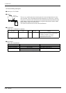
<11> LAN connector (LAN)......................... For LAN connection
<12> ExtOPT connector (ExtOPT).......... Connect the cable for addition axis control.
<13> RIO connector (RIO)........................... Connect the extension parallel input/output unit.
<14> Option slot (SLOT1, SLOT2)........... Install the interface optional. (Install the cover, when not using.)
<15> Interface cover...................................... USB interface and battery are mounted.
<16> Mode key switch................................... This key switch changes the robot's operation mode.
AUTOMATIC..........Operations from the controller or external equipment are valid. Operations for which the
operation mode must be at the external device or T/B are not possible. (Exclude the start
of automatic operation.)
MANUAL..................When the T/B is valid, only operations from the T/B are valid. Operations for which the
operation mode must be at the external device or controller are not possible.
<17> Emergency stop switch...................... This switch stops the robot in an emergency state. The servo turns OFF.
<18> Filter cover.............................................. There is an air filter inside the cover.
<19> Grounding terminal............................... The grounding terminal for connecting cables of option card. (M3 screw x 2
places)
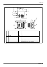
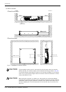
<20> Operation panel..................................... The operation panel for servo ON/OFF, START/STOP the program etc.
<21>
Display panel (STATUS.NUMBER)........... The alarm No., program No., override value (%), etc., are displayed.
<22> CHNGDISP button............................... This button changes the details displayed on the display panel in the order
of "Override" → "Program No." → "Line No.".
<23> UP/DOWN button............................... This scrolls up or down the details displayed on the "STATUS. NUMBER"
display panel.
<24> SVO.ON button ..................................... This turns ON the servo power. (The servo turns ON.)
<25> SVO.OFF button.................................. This turns OFF the servo power. (The servo turns OFF.)
<26> START button........................................ This executes the program and operates the robot. The program is run
continuously.
<27> STOP button.......................................... This stops the robot immediately. The servo does not turn OFF.
<28> RESET button........................................ This resets the error. This also resets the program's halted state and
resets the program.
<29> END button ............................................. This stops the program being executed at the last line or END statement.
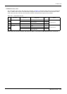
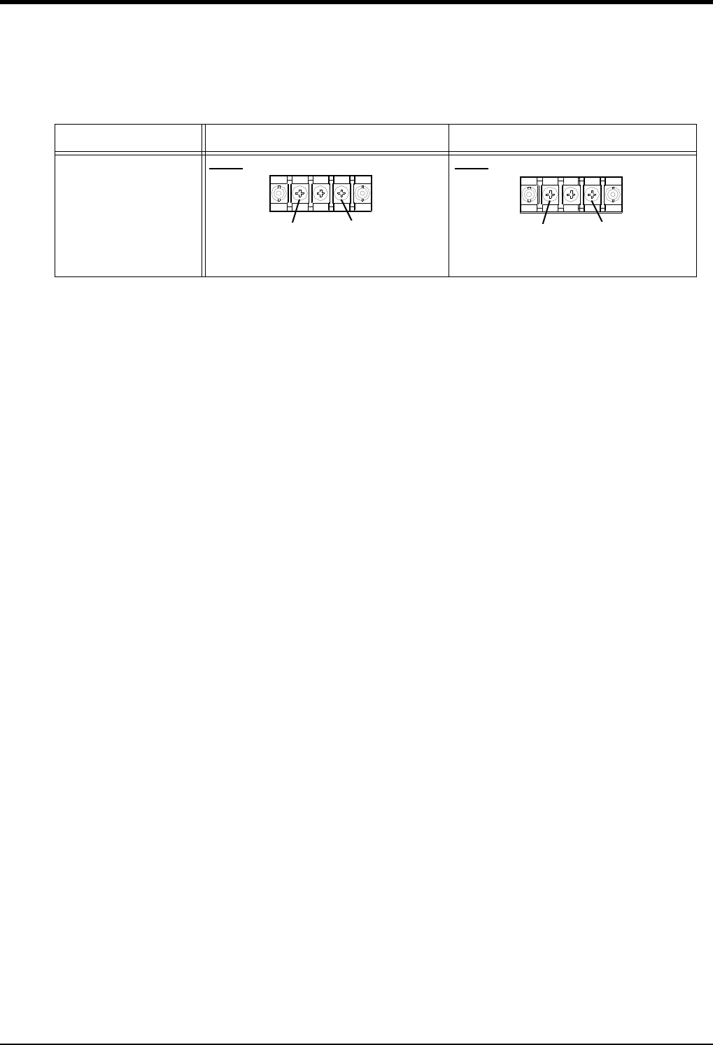
Specification
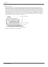
Non-CE specification CE specification
Type of ACIN terminal
Type A: For single phase
Connect the primary power supply to L1 and L2
terminal.
Type C: For single phase
Connect the primary power supply to L1 and N
terminal.
L1 L2
L1 N