


Contents
ii
Page
2.5.6 About the Installation of Tooling Wiring and Piping (Examples of Wiring and Piping) ....................... 2-39
(1) Example of wiring and piping <1> ........................................................................................................................ 2-40
(2) Wiring and piping example <2> ............................................................................................................................. 2-40
(3) Precautions for the clean specification ........................................................................................................... 2-41
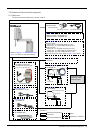
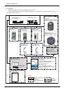
2.5.7 Wiring and piping system diagram for hand ......................................................................................................... 2-42
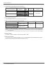
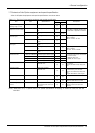
2.5.8 Electrical specifications of hand input/output .................................................................................................. 2-43
2.5.9 Air supply circuit example for the hand ............................................................................................................... 2-44
2.6 Shipping special specifications, options, and maintenance parts ...................................................................... 2-45
2.6.1 Shipping special specifications ................................................................................................................................. 2-45
(1) Machine cable ............................................................................................................................................................. 2-46
2.7 Options ....................................................................................................................................................................................... 2-47
(1) Machine cable extension ........................................................................................................................................ 2-48
(2) Changes J1 axis operating range ....................................................................................................................... 2-52
(3) Solenoid valve set ..................................................................................................................................................... 2-53
(4) Hand input cable ........................................................................................................................................................ 2-55
(5) Hand output cable ..................................................................................................................................................... 2-56
(6) Hand curl tube ............................................................................................................................................................ 2-57
(7) Internal Wiring/Piping set for hand .................................................................................................................... 2-58
(8) External Wiring/Piping box .................................................................................................................................... 2-59
2.8 About Overhaul ...................................................................................................................................................................... 2-61
2.9 Maintenance parts ................................................................................................................................................................. 2-62
3 Controller .......................................................................................................................................................................................... 3-63
3.1 Standard specifications ...................................................................................................................................................... 3-63
3.1.1 Basic specifications ...................................................................................................................................................... 3-63
3.1.2 Protection specifications and operating supply ................................................................................................ 3-64
3.2 Names of each part .............................................................................................................................................................. 3-65
3.2.1 Controller .......................................................................................................................................................................... 3-65
(1) CR750 controller ....................................................................................................................................................... 3-65
(2) CR751 controller ....................................................................................................................................................... 3-67
3.3 Outside dimensions/Installation dimensions .............................................................................................................. 3-69
3.3.1 Outside dimensions ....................................................................................................................................................... 3-69
(1) CR750 controller ....................................................................................................................................................... 3-69
(2) CR751 controller ....................................................................................................................................................... 3-70
3.3.2 Installation dimensions ................................................................................................................................................. 3-71
(1) CR750 controller ....................................................................................................................................................... 3-71
(2) CR751 controller ....................................................................................................................................................... 3-73
3.4 External input/output .......................................................................................................................................................... 3-75
3.4.1 Types .................................................................................................................................................................................. 3-75
3.5 Dedicated input/output ...................................................................................................................................................... 3-76
3.6 Emergency stop input and output etc. ......................................................................................................................... 3-79
3.6.1 Connection of the external emergency stop ...................................................................................................... 3-79
(1) CR750 controller ....................................................................................................................................................... 3-80
(2) CR751 controller ....................................................................................................................................................... 3-84
3.6.2 Special stop input (SKIP) ........................................................................................................................................... 3-87
(1) CR750 controller ....................................................................................................................................................... 3-87
(2) CR751 controller ....................................................................................................................................................... 3-88
3.6.3 Door switch function .................................................................................................................................................... 3-89
3.6.4 Enabling device function ............................................................................................................................................. 3-89
(1) When door is opening ............................................................................................................................................... 3-89
(2) When door is closing ................................................................................................................................................ 3-90
(3) Automatic Operation/Jog Operation/Brake Release and Necessary Switch Settings .............. 3-90
3.7 Mode changeover switch input ........................................................................................................................................ 3-91
(1) Specification of the key switch interface ....................................................................................................... 3-91
(2) Connection of the mode changeover switch input ..................................................................................... 3-92
3.8 Additional Axis Function ..................................................................................................................................................... 3-93