


3-85
Emergency stop input and output etc.
3 Controller
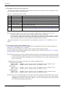
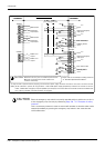
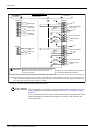
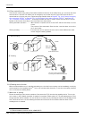
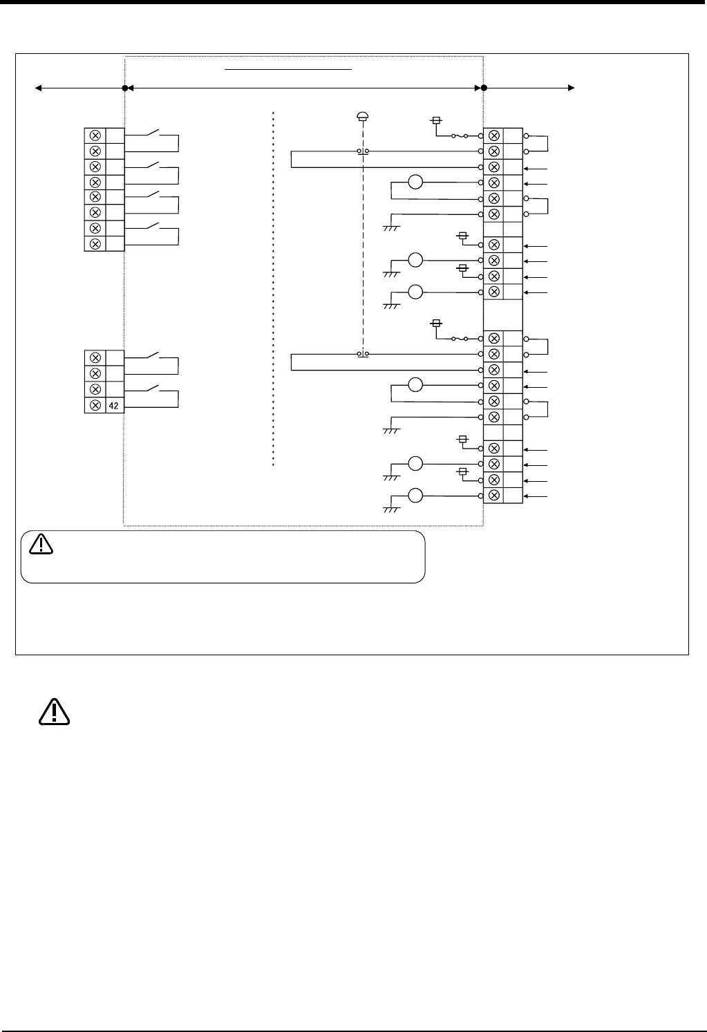
Fig.3-14 : External emergency stop connection (CR751)
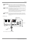
Place the emergency stop switch in an easily operable position, and be sure to wire it
to the emergency stop correctly by referencing Page 139, "6.1.7 Examples of safety
measures".
This is a necessary measure in order to ensure safe operation so that the robot can be
stopped immediately by pressing the emergency stop switch in the event that the
robot malfunctions.
CNUSR1
CNUSR2
内部回路構成
(お客様配線側)
(コントローラ側)
警告
絶縁耐圧試験は行なわないでください。
また誤って接続した場合は故障の原因となります。
CNUSR1
+24V
Relay
+24V
24G
24G
24G
RA
+24V
Relay
RA
Relay
RA
外部非常停止入力
ドアスイッチ入力
イネーブリング
デバイス入力
TB
非常停止
+24V
Relay
+24V
24G
24G
24G
RA
+24V
Relay
RA
Relay
RA
43
18
17
41
16
モード出力
非常停止出力
ロボットエラー出力
外部非常停止入力
ドアスイッチ入力
イネーブリング
デバイス入力
(お客様配線側)
短絡
短絡
短絡
短絡
モード出力
非常停止出力
ロボットエラー出力
44
19
42
17
20
45
27
28
4
29
5
30
3
2
1
26
32
33
9
34
35
8
7
6
31
10
Please refer to the example of safety measures
of "Standard Specifications Manual".
Please do not carry out an insulation pressure test.
Moreover, it becomes the cause of failure if it
connects incorrectly.
CAUTION
Internal circuit structure
(Controller side)
(Customer)
Mode output
Mode output
Robot error
output
Robot error
output
Emergency
stop output
Emergency
stop output
Short
External emergency
stop input
Short
Door switch input
Enabling device
input
Short
External emergency
stop input
Short
Door switch input
Enabling device
input
TB emergency stop
(Customer)
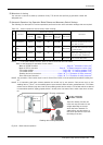
*1) This terminal is opened at factory shipping (unconnected). If power supply inside the controller is used, short-circuit the terminal.
*1)
*1)
*1)
*1)
[Note] In the customer's system, do not ground the + side of 24V power supply prepared by customer for connect to the con
-
troller. (related with emergency stop and parallel input/output) If it connects with the controller under the condition that
the + side is grounded, it will lead to failure of controller.
CAUTION