


3 Controller
Parallel I/O unit
3-120
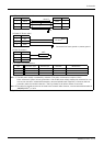
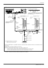
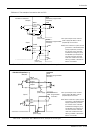
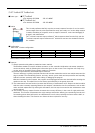
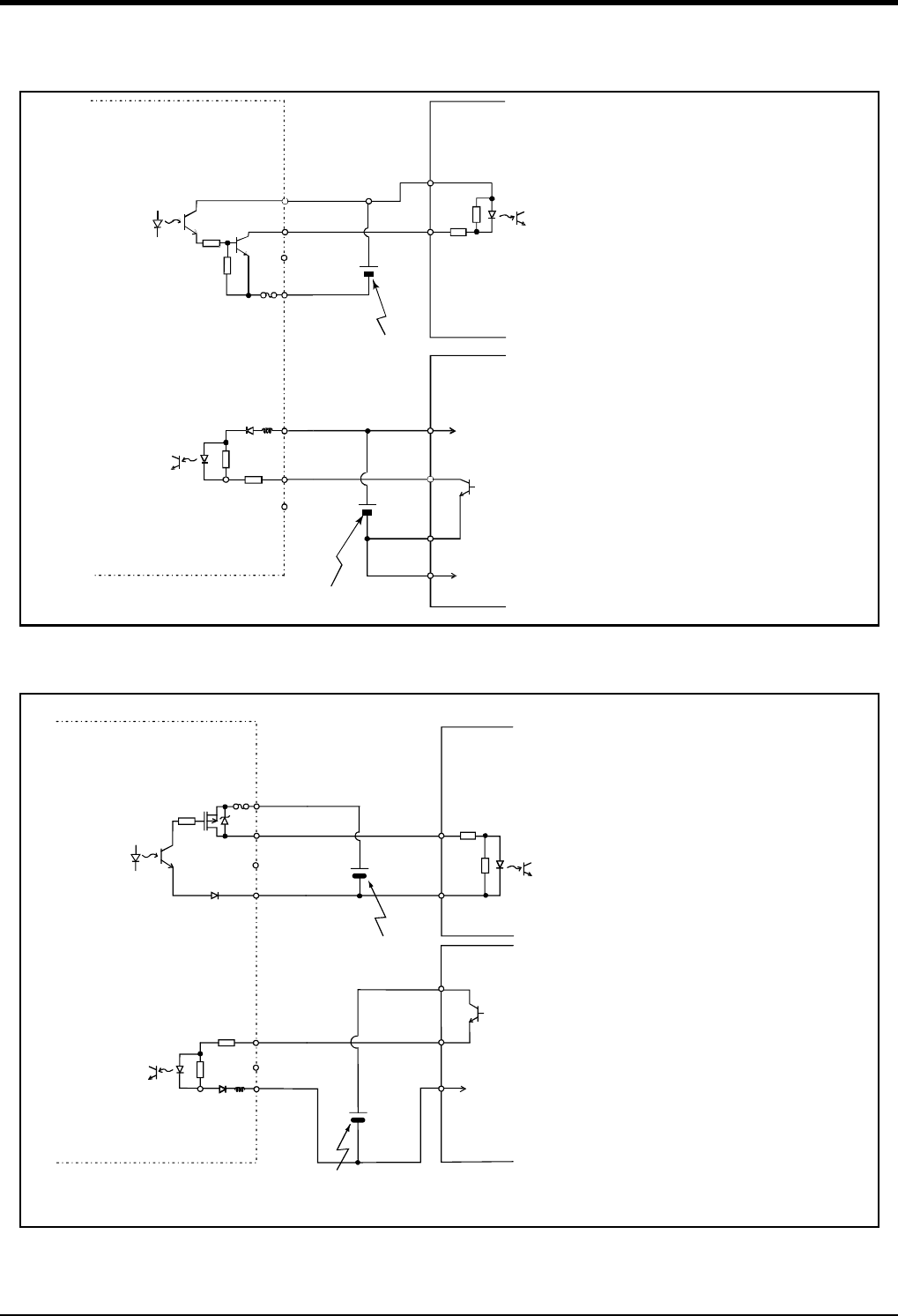
<Reference> The example of connection with our PLC
Table 3-28 : Connection with a Mitsubishi PLC (Example of sink type)
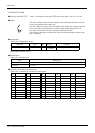
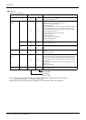
Table 3-29 : Connection with a Mitsubishi PLC (Example of source type)
60mA
(+24/+12V)
Output
Fuse
(24G/12G)
(COM)
QX41
(Mitsubishi programmable
controller)
QY41P
(Mitsubishi programmable
controller)
+24V
COM
X
Y
24V
…
…
Input
Parallel I/O interface
(Output)
(Input)
3.3K
Output
Input
External
power supply
24G
COM
External
power supply
24V
…
…
<Sink>
*The input/output circuit external
power supply (24 VDC) must be
prepared by the customer.
Note) In the customer's system, do not
ground the + side of 24V power
supply prepared by customer
for connect to the controller.
(related with emergency stop
and parallel input/output) If it
connects with the controller
under the condition that the +
side is grounded, it will lead to
failure of controller.
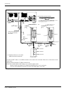
<Source>
60mA
(+24/+12V)
Output
Output
Fuse
(24G/12G)
(COM)
QX41
24G
+24V
COM
External
power supply
X
Y
24V
24V
(Output)
(Input)
3.3K
External
power supply
Input
Input
…
…
…
…
QY81P
Parallel I/O interface
(Output)
(Mitsubishi programmable
controller)
(Mitsubishi
programmable
controller)
*The input/output circuit external
power supply (24 VDC) must be
prepared by the customer.
Note) In the customer's system, do not
ground the + side of 24V power
supply prepared by customer
for connect to the controller.
(related with emergency stop
and parallel input/output) If it
connects with the controller
under the condition that the +
side is grounded, it will lead to
failure of controller.