


3-117
Parallel I/O unit
3 Controller
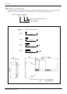
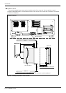
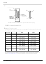
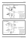
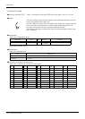
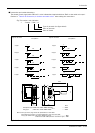
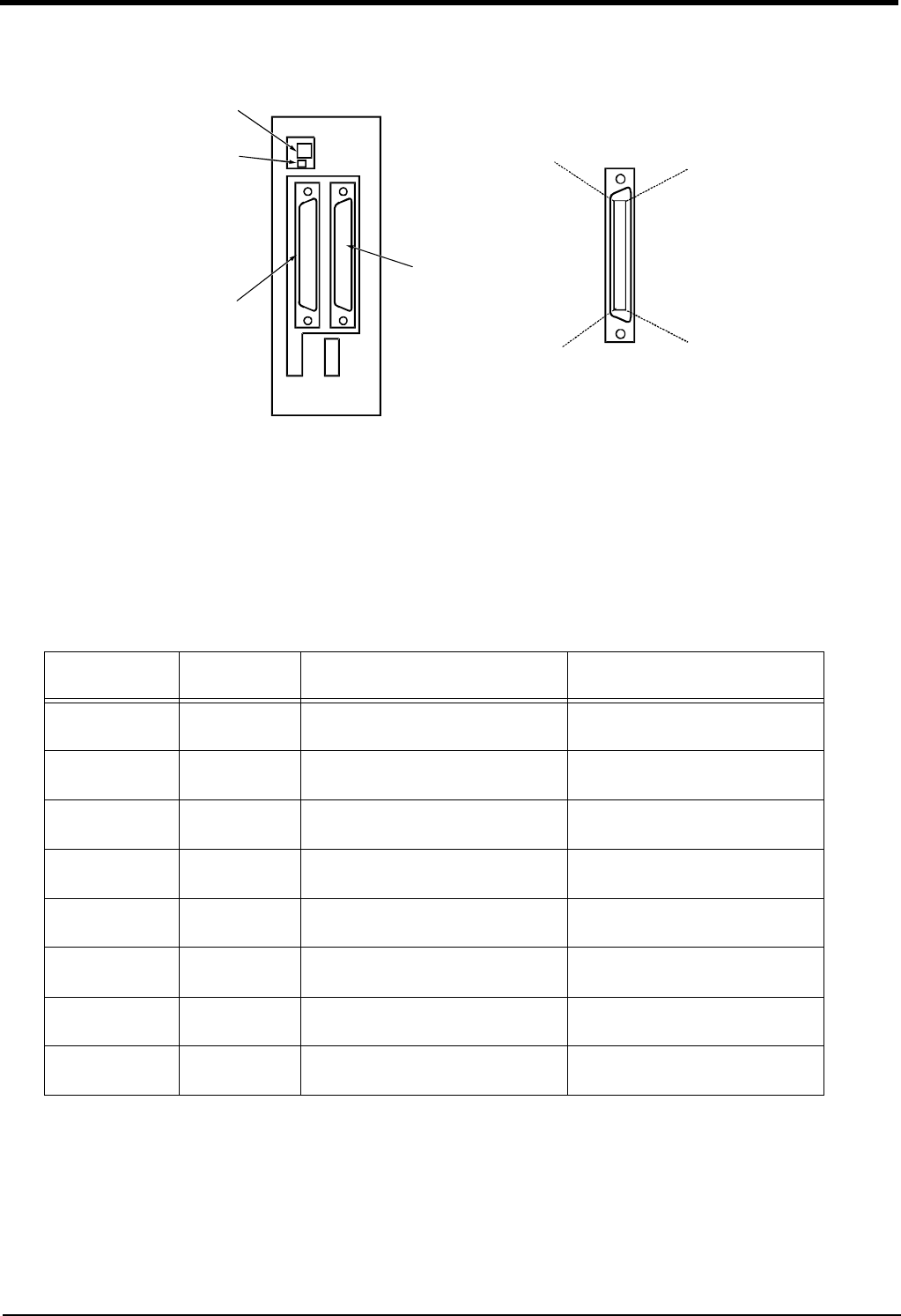
■ Pin arrangement of the connector
Fig.3-40 : Pin arrangement of the parallel I/O unit
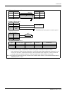
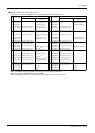
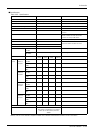
■ Assignment of pin number and signal
The assignment range of the general-purpose input-and-output signal is fixed by the setup of the station number.
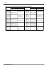
Table 3-25 : Assignment of pin number and signal
The connector pin number of the parallel I/O unit of the station number 0 and signal number assignment are
shown in Table 3-26 and Table 3-27. If it is set as other station number, please interpret and utilize.
Unit Number
Station
number
CN100 CN300
1st set 0 Input : 0 to 15
Output : 0 to 15
Input : 16 to 31
Output : 16 to 31
2nd set 1 Input : 32 to 47
Output : 32 to 47
Input : 48 to 63
Output : 48 to 63
3rd set 2 Input : 64 to 79
Output : 64 to 79
Input : 80 to 95
Output : 80 to 95
4th set 3 Input : 96 to 111
Output : 96 to 111
Input : 112 to 127
Output : 112 to 127
5th set 4 Input : 128 to 143
Output : 128 to 143
Input : 144 to 159
Output : 144 to 159
6th set 5 Input : 160 to 175
Output : 160 to 175
Input : 176 to 191
Output : 176 to 191
7th set 6 Input : 192 to 207
Output : 192 to 207
Input : 208 to 223
Output : 208 to 223
8th set 7 Input : 224 to 239
Output : 224 to 239
Input : 240 to 255
Output : 240 to 255
*2A-RZ361/2 A-RZ371 are 32/32 input-and-output units. (One-station occupancy)
50
26
25
1
Channel No. setting
TXD
LED display
Input 0 to 15
Output 0 to 15
<CN100>
<CN300>
Input 16 to 31
Output 16 to 31