


3 Controller
Parallel I/O unit
3-116
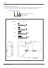
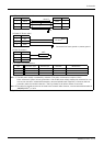
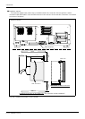
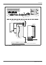
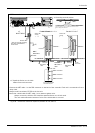
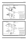
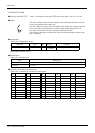
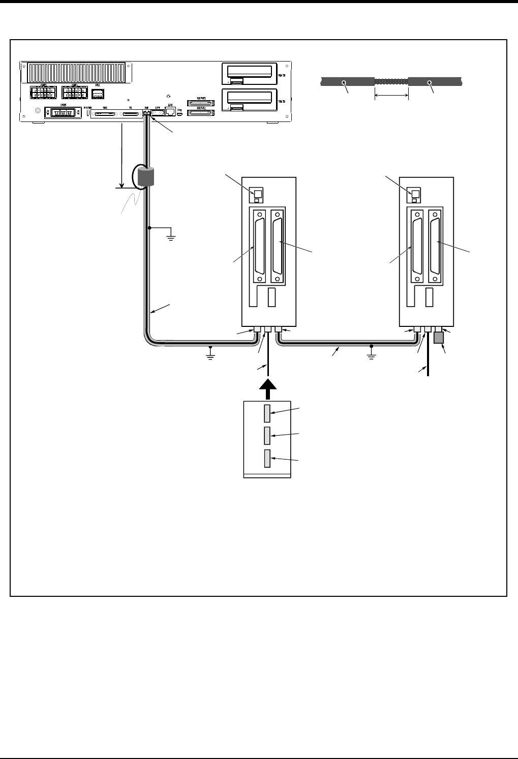
Fig.3-39 : Connection method of expansion parallel I/O unit (CR751)
局番設定
1 . . . 6
<CN100>
<CN300>
局番設定
7
<CN100>
<CN300>
NETcable-1
ケーブル
R-TM
ターミネータ
パラレル入出力ユニット 1 . . . . 6
パラレル入出力ユニット7
RIOコネクタ
DCINコネクタ
RIO2コネクタ
RIO1コネクタ
NETcable-1
ケーブル
DCcable-2
ケーブル
RIO2コネクタ
RIO1コネクタ
DCINコネクタ
前面
FG
FG
入出力ユニット底面
コネクタ配置図
注)
注)
RIO2コネクタ
RIO1コネクタ
DCINコネクタ
DCcable-2
ケーブル
100mm以内
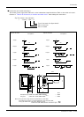
*1)
フェライトコア
(CEのみ)
FG
*2)
20~30mm
金属製ブレード部
シース
シース
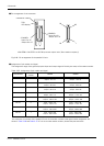
*2) ケーブルアースクランプ
シースはケーブルのコネクタ端から200~300mmの箇所を目安に
カバーの着脱ができる程度の位置で剥いてください。
※シールド線に傷をつけないようにご注意願います。
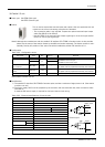
*1) Install the ferrite core in within
100mm from each connector.
RIO
Parallel I/O unit 1 . . . 6
Parallel I/O unit 7
Station No.
setting
1 . . . 6
Station No.
setting
7
Note)
NETcable-1
cable
RIO1 connector
RIO1 connector
RIO2 connector
RIO1 connector
RIO2 connector
Note)
NETcable-1
cable
DCIN
connector
DCcable-2
cable
DCcable-2
cable
DCIN
connector
RIO2 connector
DCIN connector
R-TM
terminator
I/O unit the bottom
connecter layout
Connect the NET cable-1 to the RIO connector on the back of the controller. Each unit is connected to from a
daisy chain.
Always install a terminator (R-TM) to the last unit.
Note) Use a shield cable for NET cable-1 as a measure against noise.
Always connect the shield to FG. Install the attached ferrite core in both ends.
The unit could malfunction because of noise if the shield cable is not used.
Within 100mm
Ferrite core
(Only for the CE marking/
KC mark specification)
Pass twice
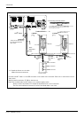
Front side
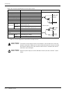
Metal braid section
Sheath
Sheath
Peel the sheath in the position about 200-300mm from the connector
end of the cable, so you can install and remove the cover.
* Don't damage the shield line.
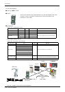
Grounding terminal position
<CR751 controller>