


4-133
List of parameters
4Software
4.2 List of parameters
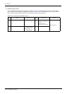
Show the main parameter in the Table 4-2.
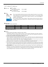
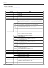
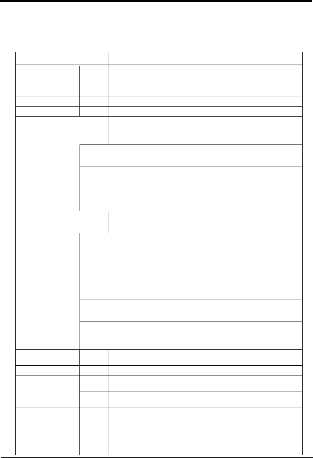
Table 4-2 : List of parameters
Parameter Details
Standard tool coordinates. MEXTL Set the default value for the tool data.
Unit: mm or deg.
Standard base coordinates MEXBS Set the relation of the world coordinate system and robot coordinate system.
Unit: mm or deg.
XYZ operation range MEPAR Designate the overrun limit value for the world coordinate system.
JOINT operation range MEJAR Set the overrun limit value for each joint axis.
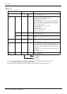
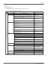
Free plane limit This is the overrun limit set with the free plane.
Create a plane with the three coordinates x1, y1, z1 to x3, y3, z3, and set the outer side of
the plane as the outside operation range (error). The following three types of parameters are
used.
SFC1P
:
SFC8P
Eight types of free plane limits can be set in SFC1P to SFC8P.
There are nine elements, set in the order of x1, y1, z1, x2, y2, z2, x3, y3, z3.
SFC1ME
:
SFC8ME
Designate which mechanism to use eight types of set free plane limits.
The mechanism No. to use is set with 1 to 3.
SFC1AT
:
SFC8AT
Set the validity of the eight types of set free plane limits.
(Valid 1/Valid 2/invalid = 1/-1/0)
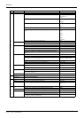
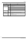
User-defined area An area (cube) defined with two XYZ coordinate points can be designated and that area set
as the outside operation range. Furthermore, a signal can be output when the axis enters
that area. Up to 32 types of area can be designated.
AREA1CS
:
AREA32CS
Specify the coordinate system of the user definition area *.
0: Base coordinate system (conventional compatibility)
1: Robot coordinate system
AREA1P1
:
AREA32P1
Designated the 1st point of the area.
There are eight elements, set in the order of x, y, z, a, b, c, L1, L2.
(L1 and L2 are the additional axes.)
AREA1P2
:
AREA32P2
Designated the 2nd point of the area.
There are eight elements, set in the order of x, y, z, a, b, c, L1, L2.
(L1 and L2 are the additional axes.)
AREA1ME
:
AREA32ME
Designate which mechanism to use the 32 types of set area.
The mechanism No. to use is set with 1 to 3.
AREA1AT
:
AREA32AT
Designate the area check type.
(Invalid/zone/interference = 0/1/2)
Zone: The dedicated output signal USRAREA turns ON.
Interference: An error occurs..
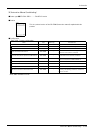
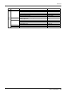
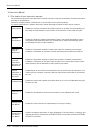
Automatic return setting RETPATH Set to restart the program after returning to the interrupt position when resuming operation
after an interruption.
Buzzer ON/OFF BZR Designate whether to the turn buzzer ON or OFF.
Jog setting JOGJSP Designate the joint jog and step operation speed.
(Set dimension H/L amount, max. override.)
JOGPSP Designate the linear jog and step operation speed.
(Set dimension H/L amount, max. override.)
Jog speed limit value JOGSPMX Limit the operation speed during the teaching mode. Max. 250[mm/s]
Hand type HANDTYPE Set the hand type of the single/double solenoid, and the signal No.
(Single/double = S/D)
Set the signal No. after the hand type. Example) D900
Stop input B contact desig
-
nation
INB Change the dedicated input (stop) to either of normal open or normal close.